Recycling of Vaisala RS-41 meteorological radiosonde
Since I succeeded in capturing a few Vaisala
RS-41 meteorological radiosondes, I decided to look for some usefulness
for
them. Since the frequency at which these radiosondes are transmiting,
is
protected and allocated to meteorologists, it is necessary to find a
way to shift the frequency into the amateur or ISM band. The radiosonde
uses
a Si4032-type radio IC so this job is only a question of programming.
Unfortunately, it is usual practice that the program in these devices
is protected so that only one way can be walked - the whole program
must be re-written. During the search on the net I came across a
program published by a Polish radio amateur, SQ5RWU. I programmed a
radiosonde with this software and started testing it. The program
worked,
but it was unconfortable that every time I wanted to change some
parameters, it was necessary to change the source code and compile it
and then re-write the new program into the processor. This is a
time-consuming process, and the flash memory on the other hand does not
like the frequent rewriting. Since the whole program was simple and the
possibilities it provided me were not enough, I decided to re-write the
entire program. The final result of this development is this program.
It is quite large, barely fitting in the flash, but the advantage is
that you does not have to constantly re-write the radiosonde. The
program
should be put once into it, then the parameters can be changed at any
time through the serial line on the port of the rs41 connector.
Before the first programming, the flash memory must be deleted
completely with the "Full chip erase" command so that the originally
protected memory parts are released. Otherwise, the program will not
save our own parameters due to lack of space!
Description:
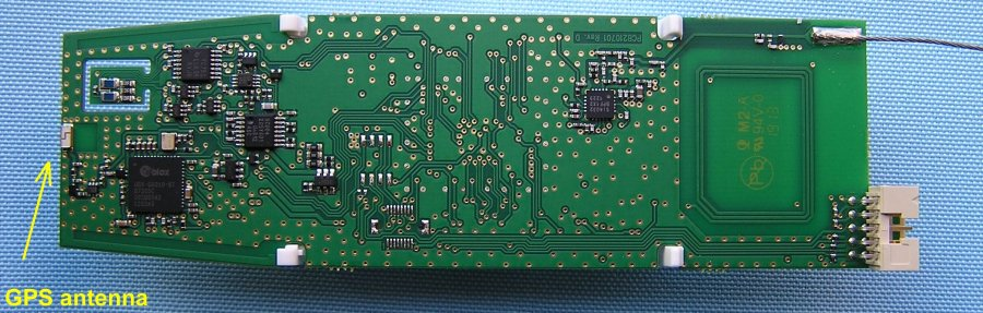
The radiosonde can be switched on by the
pushbutton
in the lower right corner. If the battery voltage is sufficient (the
radiosonde can be powered by two NiMH batteries), the green LED on the
lower
left corner of the PCB will start to flash. If
the radiosonde has a good view on the GPS satellites, the green LED will
light up permanently after finding it's position. The red LED near to
it lights up when the transmitter is working. The original sensors are
not used, so they must be removed. If the BUTTON parameter is set to
ON, the radiosonde can be switched off by pressing and holding the button.
Push the button until the green LED starts blinking rapidly. After the
button has been released, the radiosonde switches off. If the BUTTON is OFF,
the radiosonde can only be switched off by removing the batteries from the
battery holder.
The radiosonde can operate in RTTY, APRS and CW
mode.
These modes can be switched on or off individually. The RTTY text is
compatible with UKHAS recommendations. The APRS packet may be decrypted
and encoded according to Mic-E variable. Sonde transmissing APRS data
only if the coordinates are valid. Each parameter can be changed
by sending a command and its parameters by the serial port. To do this,
the radiosonde and computer should be connected via a COM-TTL or
USB-TTL
converter. Please note the radiosonde connector on the UART port is
3.3V!
You can use any terminal program on your computer. The speed is 9600
baud, 8 data bits and 1 stop bit without parity and hw control (9600
8-N-1). As every other parameters, this can be changed too. The possible speeds are from 300 to 115200 baud. Communication
is interactive. All issued commands will be answered. If the processor
has understood and executed the command, then the answer will be an OK.
Otherwise, we'll get an error message telling you where we made a
mistake. After turning on the radiosonde, we need to see this welcome text
on the screen, if the radiosonde and computer are properly connected:
STM32 CW, RTTY & APRS tracker v. 2.5 by OM3BC...
cmd>
If you need help, you can use the HELP or the ? commands. After this command we get the following text:
cmd>help
Allowed commands (not case sensitive):
BUTTON on/off - use button to turn off
LEDS on/off - use LEDs
POWER n - rf power n = 0 to 7 (7 is max.)
HOLDOFF n - n = time between two rtty messages in seconds
SERCOM n - speed of serial communication port (n = 300 to 115200)
RTTY on/off - send rtty message
RTTYFRQ n.n - n.n = rtty and cwid frequency in MHz
RTTYCALL string - rtty callsign (up to 15 characters)
BAUD n - n = rtty baudrate (max. 300)
DBITS n - n = rtty databits (7 or 8)
SBITS n - n = rtty stop bits (1 or 2)
SHIFT n - n = 1,2,3,4 or 270,540,810,1080 Hz
TEMP (or TEMPERATURE) on/off - send temperature in rtty messages
ALT (or ALTITUDE) on/off - send altitude in rtty messages
SPEED on/off - send speed in rtty messages
COURSE on/off - send course in rtty messages
UBAT on/off - send battery voltage in rtty messages
RTTY_WWL n - n = characters of wwlocator (only even numbers) in rtty messages
RTTY_TIME on/off - send time in rtty messages
SAT (or SATELLITES) on/off - send heard satellites in rtty messages
APRS on/off - send aprs messages
APRSFRQ n.n - n.n = aprs frequency in MHz
APRSCALL string - aprs callsign (up to 6 characters)
SSID n - aprs ssid n = 1 to 15
APRS_ALT on/off - send altitude in aprs ttext
SYMBOL string - symbol from aprs symbol table (2 characters)
RELAY string - aprs relays (WIDE1-1,WIDE2-1)
APRS_EVERY n - time between aprs messages is n x holdoff
TAIL_EVERY n - time between tail text is n x aprs time, 0 = no tail text
TTEXT string - tail text (up to 100 characters)
APRS_UBAT on/off - send battery voltage in aprs ttext
APRS_TEMP on/off - send radio chip temperature in aprs ttext
CWID on/off - send cwid messages
CWIDMESS string - cw message (up to 25 characters)
CWID_ALT on/off - send altitude via cw
CWID_UBAT on/off - send battery voltage via cw
CWID_WWL n - n = characters of wwlocator (only even numbers) in cw messages
CWID_EVERY n - time between cw messages is n x holdoff
CW_SPEED n n = cw speed in wpm
DISP - show parameters
DEF - set default values
SAVE - save parameters to flash
cmd>
Available commands:
BUTTON - this parameter specifies whether the push button can be used to turn off the radiosonde or not.
LEDS - you can save energy when
you do not use LEDs. Nobody sees them anyway when the radiosonde is
flying. After switching on, the LEDs always work, but when set to OFF,
they automatically turn off after 10 minutes of operation.
POWER - output power setting 0 = smallest, 7 = maximum power (approx. 40 mW).
APRSFRQ - APRS frequency (recommended frequency is 432,500 MHz)
RTTYFRQ - RTTY frequency. This frequency is also valid for CW identification.
APRSCALL - APRS call sign.
RTTYCALL - RTTY call sign.
CWIDMESS - the text of the CW identification.
If you write a > at the beginning of the text, the broadcast will
begin with a "attention" (-.-.-) sign, which facilitates machine
decoding (MixWin, Dl-FlDigi, etc.).
RTTY - RTTY Text On / Off.
HOLDOFF - the time between the two RTTY broadcasts.
BAUD - RTTY transmission speed in baud (max. 300).
DBITS - number of data bits. Possible values are 7 or 8.
SBITS - number of stop bits. Possible values are 1 or 2.
SHIFT frequencies. Possible values: 1-270, 2-540, 3-810, 4-1080 Hz
TEMP - to transmit the temperature in the RTTY text. (The value is the temperature of the radio chip, not the environment.)
ALT - enable altitude transmission.
SPEED - enable speed transmission.
COURSE - enable motion direction transmission.
UBAT - enable battery voltage transmission.
SAT - the number of GPS satellites heard.
APRS - Enable APRS transmission.
SSID - the caller ID of the APRS. Possible values from 0 to 15.
RTTY_TIME - send time in RTTY messages.
SYMBOL - two characters that determine how the radiosonde appears on the www,aprs.fi website. Icon from the symbol table
RELAY - aprs relays (WIDE1-1,Wide2-1).
APRS_EVERY - APRS packages are not required to be given too often. This parameter specifies the time between the two packets.
TAIL_EVERY - frequency of transmission of the attached information text (comment field).
TTEXT - the attached information text (comment).
APRS_UBAT - Send battery voltage in aprs text.
APRS_ALT - Send altitude in aprs ttext.
APRS_TEMP - Send radiochip temperature in aprs ttext.
CWID_WWL or RTTY_WWL- Send n charakters of WW Locator. n = 0 for no WW Locator
CWID - Enable CW Authentication.
CWID_EVERY - Frequency of CW identification.
CW_SPEED - the CW identification speed in WPM.
DISP - shows the set parameters.
SERCOM - speed of serial communication port (n = 300 to 115200).
DEF - set parameters to default values.
SAVE - stores the set parameters.
One possible setting:
cmd>disp
Current parameters:
BUTTON ON
LEDS OFF
POWER approx. 100 mW
UART 9600 8-N-1
HOLDOFF 10 s
RTTY ON
RTTY and CWID FREQUENCY: 434.500 MHz
RTTY CALLSIGN: OM3BC/AM
RTTY BAUDRATE: 100 Bd
RTTY SHIFT: 540 Hz
RTTY DATA BITS: 7
RTTY STOP BITS: 2
RTTY TEMPERATURE: OFF
RTTY ALTITUDE: ON
RTTY SPEED: OFF
RTTY COURSE: OFF
RTTY BATTERY VOLTAGE: ON
RTTY SATELLITES: ON
RTTY WWL: OFF
RTTY TIME: ON
APRS ON
APRS FREQUENCY: 432.500 MHz
APRS CALLSIGN: OM3BC-11
APRS RELAY: WIDE1-1
APRS SYMBOL: /O
APRS EVERY: 1
APRS ALT: ON
APRS TAIL TEXT EVERY: 1
APRS TAIL TEXT: Modified RS-41 balloon tracker
APRS UBAT: ON
APRS TEMP: ON
CWID ON
CWID MESSAGE: TEST DE OM3BC/AM
CWID speed: 60 WPM
CWID EVERY: 5
CWID WWL: 6 characters
CWID UBAT: OFF
CWID ALT: OFF
cmd>
Closing remarks:
The original source can be found here.
Hex file can be found here.
For programming, I use the ST-LINK V2 programmer, which can be obtained from aliexpress, for example.
HG8LXL, Laci's report on the balloon, he has launched.
Wiring:
RS-41 connector:
| ----------- |
| 2 4 6 8 10 |
| 1 3 5 7 9 |
| ------ ---- |
1 - GND
2 - Uart3 Rx
3 - Uart3 Tx
4 - PB1 * (10k + cap + 10k)
5 - Vcc (Boost out)
6 - VBAT
7 - RST
8 - SCL
9 - SDI
10- GND
The Programer cable connections:
RS41 ----- ST-LINK
===================
Pin 1 ----- GND
Pin 5 ----- 5.0V
Pin 8 ----- SWCLK
Pin 9 ----- SWDIO
USB - TTL converter:
RS41 ------ USB-TTL
===================
Pin 1 ----- GND
Pin 2 ----- TxD
Pin 3 ----- RxD
From January
2024, a new type of processor will be installed in the RS41. It has a
larger flash memory and consumes less power. Although the old and new
processors are pin-compatible, unfortunately, the same pins are not
used in all cases. Because of this, the old program cannot be used in
the new hardware. Since the firmware had to be modified anyway, it was
time for a little wrinkle-removal. Lately, the RTTY mode has been
pushed into the background, and HORUS is used instead. This is
understandable to a certain extent, although I don't appreciate the
fact that an identifier has to be requested centrally, and someone else
decides what identifier a probe can fly with. Since HORUS uses 4FSK
modulation, the transmission of a packet takes much less time than in
the case of RTTY. That is why this mode was also included in the new
firmware.
The information and advice written about the hardware are also valid here.
This firmware can now handle external sensors, so if
the sensor is not damaged, we can use it (although this increases power
consumption).
The serial port parameters are still 9600N1.
After switching on, the probe logs in with the following message: RS41
based payload for STM32F100 (RS41 based payload for STM32L412).
You can use the HELP, H or ? command to find out what commands to use and in what form.
You can view the current parameters with the DISP command.
As a first step, we change N0CALL to our callsign (APRS and RTTY).
After that, we can modify the other parameters. After programming, none
of the modes are enabled. Enable the ones we want to use.
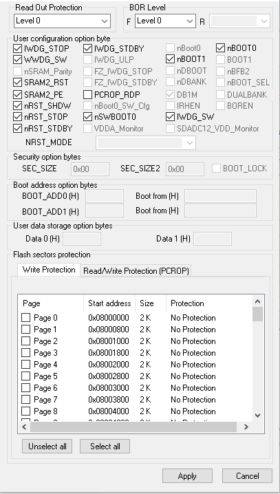
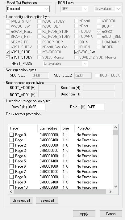
If the program does not start after loading, check whether the correct config bits are set in the programmer.
STM32L412
STM32F100
firmware for probes before 2024 (STM32F100 with V included).
firmware for probes from 2024 and later (STM32L412 starting with W).
The parameters of the new firmware are slightly different from the original firmware parameters:
Set parameters
APRS: OFF
APRS CALL: OM3BC
APRS Frequency: 432.500 MHz
APRS Comment: RS41 based payload
APRS SSID: 11
APRS Symbol: O
APRS Symbol Table: /
APRS MODE: NORMAL
APRS HAB: OFF
APRS MIC-E: ON
RTTY: OFF
RTTY CALL: OM3BC
RTTY Frequency: 434.600 MHz
RTTY Bits: 7
RTTY Stop Bits: 2
RTTY Baudrate: 100
RTTY Shift: 2 (540Hz)
HORUS: PRIMARY
HORUS ID: 730
HORUS Primary Frequency: 437.600 MHz
HORUS Secondary Frequency: 434.715 MHz
HORUS Baudrate: 100
MORSE: OFF
MORSE Frequency: 434.600 MHz
MORSE Speed: 40
MORSE Mode: REDUCED
MORSE WWL characters: 6
MORSE Altitude: OFF
MORSE Comment:
RADIO POWER: 7
HOLD OFF: 30
UART Baudrate: 9600
>
HELP:
Available commands
command<SPACE>parameter<ENTER> (commands allways without <SPACE>!)
disp (set parameters)
horusfrq frequency (primary in Hz, kHz or MHz)
horus2frq frequency (secondary in Hz, kHz or MHz)
aprsfrq frequency (in Hz, kHz or MHz)
rttyfrq frequency (in Hz, kHz or MHz)
morsefrq frequency (in Hz, kHz or MHz)
holdoff time (time in sec. minimum 10s)
horusenable x (off/primary/secondary/both/alt or 0/1/2/3/4)
aprsenable x (OFF or 0-disable ON or 1-enable)
rttyenable x (OFF or 0-disable ON or 1-enable)
morseenable x (OFF or 0-disable ON or 1-enable)
aprsmsg comment (aprs comment max. 120 char)
aprscall call (max 6 char)
rttycall call (max 15 char)
horusid x (Payload ID)
horusbdr x (horus baudrate)
rttybdr x (rtty baudrate)
rttybits x (7 or 8)
rttystop x (1, 1.5 or 2)
rttyshift x (shift = x * 270Hz)
aprsssid x (0 to 15)
aprssymbol x (symbol from aprs table)
aprstable x (aprs symbol table / or )
aprsmode x (0-normal, 1-wx)
aprshab x (OFF/ON or 0/1)
aprsmice x (OFF/ON or 0/1)
morsespeed x (WPM)
morsemode x (0-reduced, 1-full)
morsewwl x (4,6,8,10)
morsealt x (OFF or 0-disable ON or 1-enable)
morsemsg comment (morse comment max. 60 char)
holdoff time (time in sec. minimum 10s)
radiopwr x (0-7)
uartbdr x (1200,2400,4800,9600,19200,38400,57600,76800,115200)
>
There must be a space or an equal sign between the command and the parameter.
After loading the firmware, only the HORUS mode is
active on the 437.6 MHz frequency. If we want to use other modes, we
must enable them via the serial port with one of the enable
(aprs,rtty,morse) commands. In the case of HORUS, we can use two
different frequencies. The primary one is 437.6 MHz (usually used by
probes). As more and more stations operate in the 70cm band, it may be
preferable to use another frequency, or to combine two frequencies. The
commonly used backup frequency is 434.715 MHz. Of course, we can set
any frequency we deem appropriate for either the primary or secondary
frequency, although this risks the fact that others will not receive
our probe. After the horusenable command, we can write a number or
text, where 0 or off means that this mode is disabled, 1 or primary if
we only want to use the primary frequency, 2 or secondary if only the
secondary one, or 3 or both if we want to transmit on both frequencies
in every period, or the 4 or alt parameter if we want to use the two
frequencies alternately (primary in one period, secondary in the
second).
If we want our sonde to be listed on the
amateur.sondehub.org website in APRS mode, then set the aprshab and
aprsmice parameters to ON in the APRS parameters.