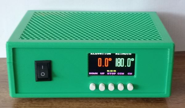
The controller is primarily designed for BIGRAS rotators, but it can also be used for other rotators that use pulse feedback. By turning off the vertical rotation, full use of RAK or BIGRAK rotators is also possible. In the case of a small modification of the firmware, it can also be used with analog feedback (YAESU). Three sizes of displays can be used for the controller. 1.9" like in the picture, as well as 2.4" and 2.8". It is important the display needs to have an ST7789 type chip.
Available functions:
The controller can be controlled in four ways. One of the two USB ports on the board is a native USB 1.1 type, with a speed of 12 Mbps. The other USB port is a USB-UART converter, its transmission speed is fixed at 115200 Bd. In addition, a standard RS232 COM port can be used via a TTL-RS232 converter. Its speed can be set between 300 and 230400 Bd. With the right program, it is also possible to control via WiFi. The mentioned options can even be used at once. The settings are also available either directly from the controller, via a serial port, or via WiFi, in which case we can change the settings by opening the appropriate web page. The main commands of the controller are compatible with the Yaesu GS232, so it should be selected if necessary. The full command set is available through the serial port with the H command. In addition to Yaesu commands, it can interpret FOXDELTA type commands as well as standard NMEA type GPGGA messages. If we have previously set our own coordinates, it calculates the azimuth and elevation of the given point based on the data in the messages, and then turns the antenna in the direction of the given point. This function is mainly used for tracking high-altitude balloons (for example, the program called SondeMonitor has such an output, so this program can rotate the antenna straight). The controller can also emulate the PSTRotator and rotctld programs. So if in one of the programs we use the control of the rotor is only possible with the PSTRotator or rotctl protocol (e.g. SatDump, Horus), we just need to set the appropriate port number in both places, and in the program we use the controller's IP address, which we see in the upper left corner of the Menu window. Of course, it is necessary to be connected to the WiFi network.
Description:
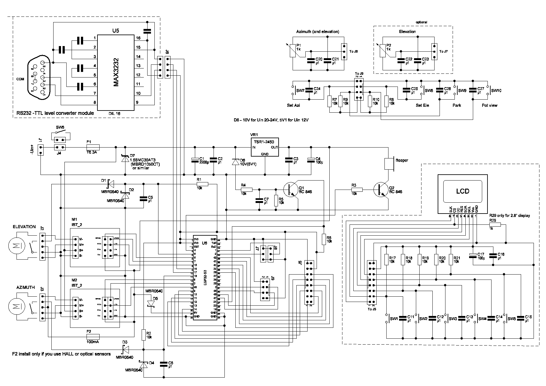
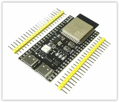
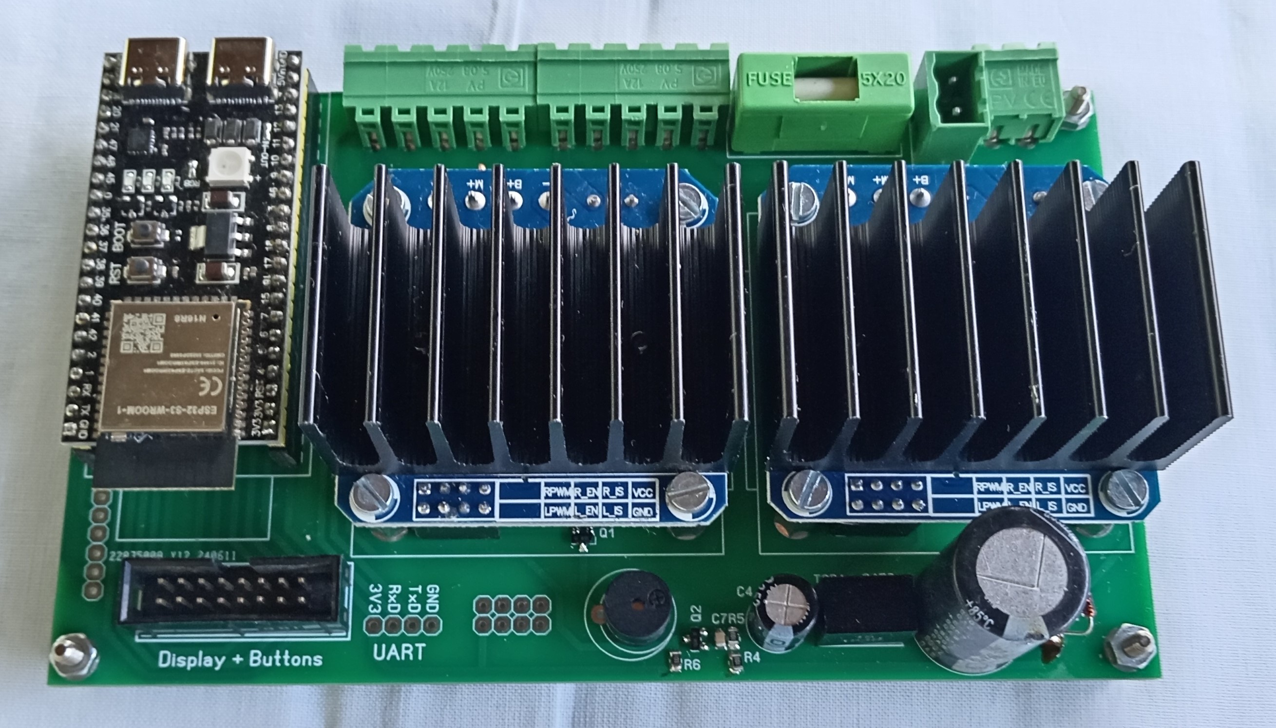
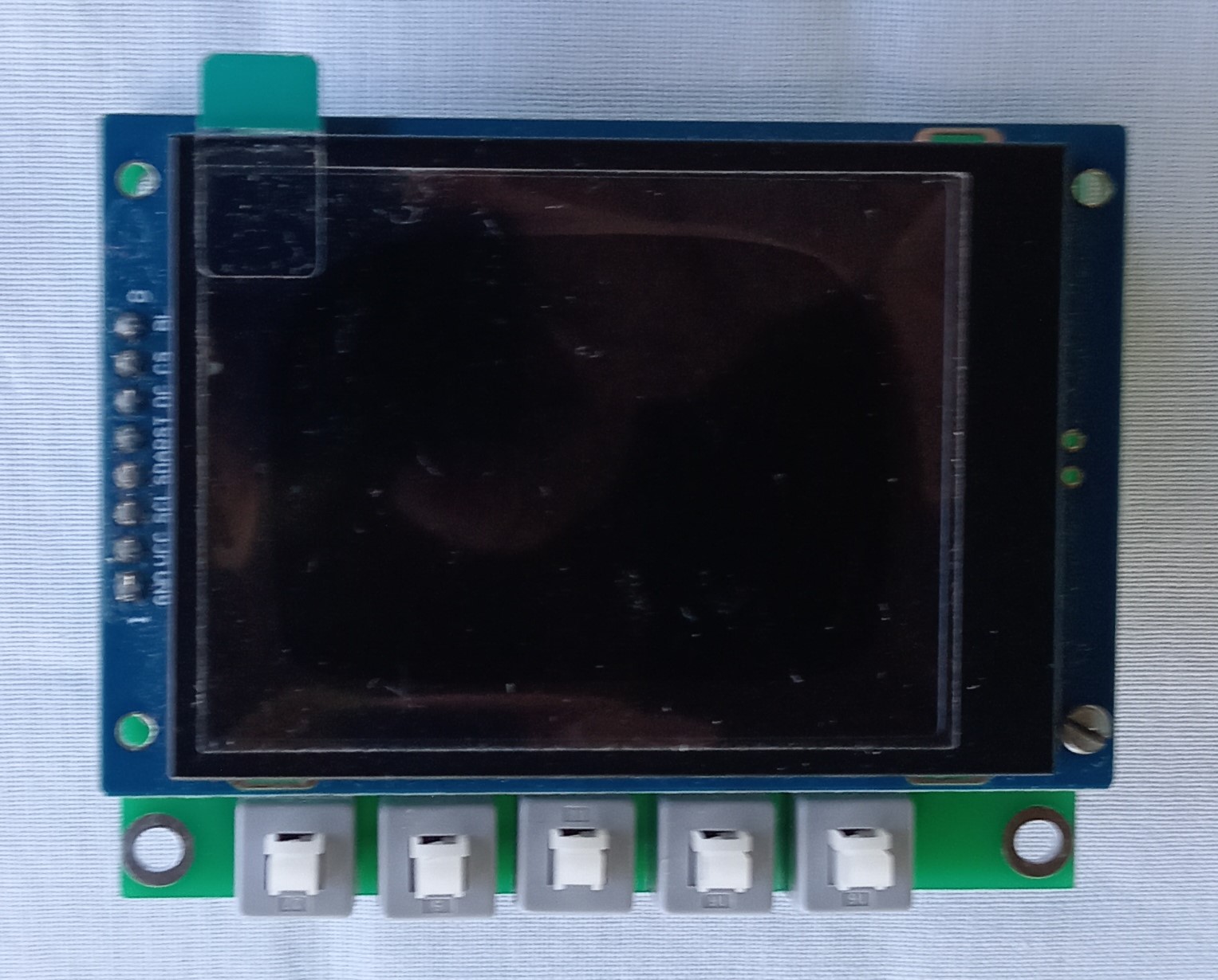
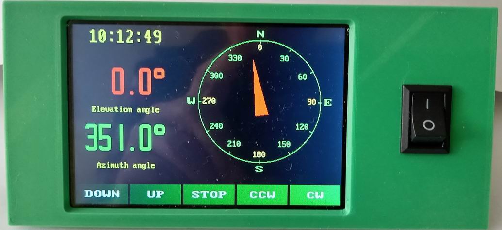
The central element of the control circuit is an ESP32-S3 N16R8 type module. We need to get the module shown in the picture, because there is also a version on the market where the push buttons are directly above the USB connectors. However, this module is 2.54 mm narrower, so it will not fit into the PCB due to the pins location. Some manufacturers sell the module with a loaded demo program, which flashes the LED on the module after switching on. If you managed to get one like this, you have to dismantle the short circuit marked RGB on the module. Next to the RGB LED is another short cut labeled IN-OUT. This has to be cut short! A uPython interpreter runs in the module, which interprets and executes the code written in Python. In order to simplify the preparation, a ready-made module of type IBT_2 was used for controlling the motor itself. The display and push buttons are located on a separate small panel. Since the COM connections are already obsolete, it would not have been reasonable to integrate it on the PCB, but if necessary, this module can also be connected separately. There are 5 push buttons on the display panel. Their function depends on the current situation. The function of which button is indicated in the bottom line of the display. If both horizontal and vertical rotation are active, then from left to right: antenna down, antenna up, stop or menu, antenna to the left (counter-clockwise), antenna to the right (clockwise). If only horizontal rotation is active, the far left button is left turn, the right far button is right turn, the middle one is stop. The second and fourth buttons have no function.
The use of the following functions is only for convenience and does not affect the main functionalities of the controller. Their installation is not absolutely necessary. The P1 and P2 potentiometers can be used to turn the antenna to the desired position more easily, by setting the desired direction with the potentiometer, then pressing the SW7 button, the antenna moves horizontally, while pressing the SW8 button, the antenna moves vertically, to the selected position. We can use a common potentiometer for the horizontal and vertical directions, or a separate potentiometer for the horizontal and one for vertical directions. If the value of the pot parameter in the rotor_s3.cfg file is 1, it assumes a common potentiometer, if the value is 2, it means that there are two separate potentiometers. Since this parameter is not changed during use, this parameter can only be rewritten manually with a text editor in the previously mentioned file. When the third push button (SW9) is pressed, the antenna moves to the parking position set in the menu. So that the potentiometers does not have to be calibrated, when SW10 is pressed, the position set with the potentiometers is shown on the display. Thus, when turning the potentiometers, we can see where the antenna will turn when SW7 or SW8 is pressed.
The main commands that can be used to rotate the antenna:
Waaa eee - turn the antenna horizontally to aaa, vertically to eee
A - stop azimuth turning
AZ=aaa - turn the antenna horizontally to aaa
AZ=aaa EL=eee - turn the antenna horizontally to aaa, vertically to eee
E - stop elevation turning
EL=eee - turn the antenna vertically to eee
S - stop all turning
Maaa - turn the antenna horizontally to aaa
Keee - turn the antenna vertically to eee
ML - turn the antenna counterclockwise
MR - turn the antenna clockwise
MU - turn the antenna up
MD - turn the antenna down
L - turn the antenna counterclockwise
R - turn the antenna clockwise
U - turn the antenna up
D - turn the antenna down
C - the current position of the antenna in the horizontal direction
C2 - the current position of the antenna in horizontal and vertical directions
B - the current position of the antenna in the vertical direction
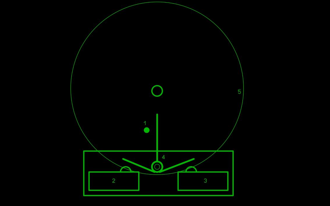
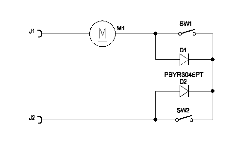
For the antenna calibration to work properly, a limit switch must be built into the rotary mechanism, which in the initial position stops the rotation in the horizontal direction. Such a limit switch is originally built in vertically, but in the horizontal direction - for reasons incomprehensible to me - it does not exist, so we have to build it ourselves. It's not too difficult to solve, but it requires a bit of creativity depending on who has what tools and limit switches available. In all cases, make sure that the switch is active in only one direction. One possible solution is shown in this figure. In this figure:
1 - vertical rod on the gear
2.3 - limit switches
4 - lever for switching limit switches
5 - gear
6 - auxiliary panel on which the lever shaft and limit switches are mounted
The advantage of this solution is that the limit switch is in both directions and the required range of rotation can be set by correct adjustment of the lever arms. The antenna should be mounted on the rotor so that the overturning is the same on both ends. In this case, the value of the overturning in the counterclockwise direction is entered as the azimuth offset value in the menu.
Limit switch connection:
Settings:
The most important parameters can be accessed in the menu. You can get here by pressing the middle button (STOP) for a long time. In this case, a multi-line menu appears in which you can scroll to the appropriate menu item. These are the following:
AZ turn to: here you can set where the antenna should turn horizontally when you exit the menu
EL turn to: here you can set where the antenna should turn vertically when you exit the menu
Pulse/degree: here you can set how many pulses the rotator gives for turning 1 degree
Azim offset: how many degrees is the zero point of the antenna from the left end position
Elev. offset: how many degrees is the horizontal position from the limit switch
Max. azimuth: the position of the antenna in the right end position
Max. elevation: the maximum permitted elevation in the antenna system's vertical beam (90 or 180 degrees)
GS232: A or B, depending on which type you emulate
Beeper type: if the value is OFF, the beeper is turned off, it does not sound if a command is received on the serial port, DC - in case of an active beeper, or a number that represents the frequency of the beeper. Its value can be between 200 and 5000.
Elevation: ON or OFF, if the rotator is not suitable for vertical rotation, set this parameter to OFF
Overturn: ON or OFF, if the antenna allows overturning, then by switching this parameter to ON, the rotator can be used continuously between the value set with the horizontal offset and max. azimuth. In the OFF state, only between 0 and 360.
Autoturn: in the ON state, if the CW, CCW, UP or DOWN button is pressed for 5 seconds, then after the button is released, the antenna continues to rotate until either one of the buttons is pressed again, or the rotator reaches the end position.
Zero point: this parameter determines where the mechanical zero point of the rotator is, it can be south or north
WiFi: how WiFi should behave at startup. You can turn it off or set it to try to connect to the WiFi network at startup. If that doesn't work, switch to AP mode.
Backlight: the intensity of the background light
COM baudrate: speed of the serial port
Menu char.: font size of the menu - larger letters have better readability, but fewer lines, or smaller letters for more lines visible
Screensaver: in case of 0, it is switched off (the display lights up continuously), in case of a number, the display switches off after this number of seconds
Display type: display type, 1.9, 2.4, 2.8 col
Minimal turn: The minimum rotation speed of the rotator at which the antenna still rotates reliably. When starting, it accelerates from this speed to the maximum speed, before stopping it slows down to this speed so that the rotor is not hit by strong impacts. Thanks to this, the movement is more continuous even when tracking a satellite.
Background: color combinations used on the display
Timezone: set your own time zone if you don't want to see the time in UTC. (Time difference between UTC and winter time. Daylight saving time is set automatically)
Calibrate to calibrate the rotator position. In the horizontal direction, it can only be used with the subsequent installation of the limit switches, in the vertical direction, the limit switch is already installed at the factory
If the WiFi SSID and password are set correctly, you will see the received IP address in the upper left corner of the menu window. We can access the settings page in a browser using this IP address. The firmware version is in the upper right corner. In case of a successful connection, the UTC or local time, based on the timezone setting, is displayed in the lower section of the screen.
Website with settings:
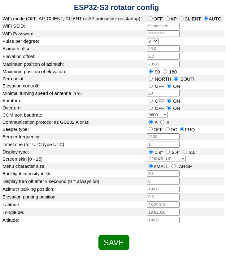
A file named rotor_s3.cfg can be found in the memory. It contains the set values of the parameters. It's a text file, but I recommend editing it by hand only if you know what you're doing. Manual editing can be beneficial when entering the SSID and password for the first time, if we do not want to connect via the AP number 192.168.4.1. However, setting the SSID and password can be done in a much more secure way via the serial port with the { and } commands. If the controller cannot connect to the WiFi network, and if this function is not disabled, it creates an AP that can be reached either with the ROTOR-AP SSID or with the IP address 192.168.4.1. In this case, the password is 1234567890. If you want to use WiFi, make sure to check in the menu whether WiFi is ON. If not, turn it on. In this case, automatic connection is in effect (the controller must be restarted, because it only checks the settings when it is switched on). We can change this setting via the website.
The third way to set the parameters is to send the appropriate commands on the serial port. The list of commands can be retrieved with the command H or h.
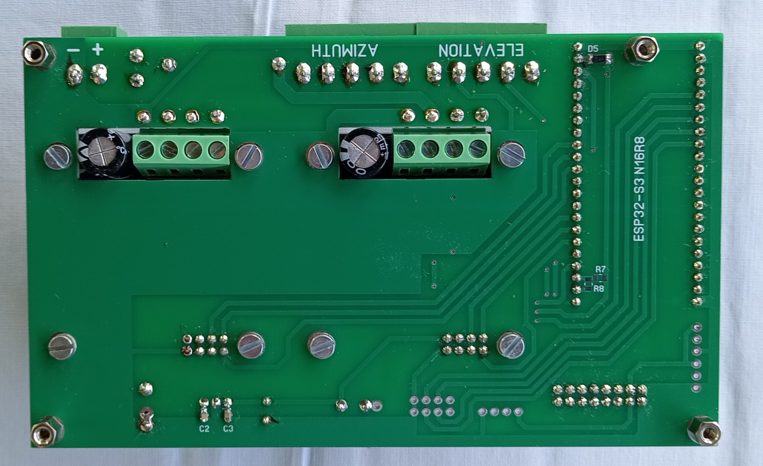
Assembly:
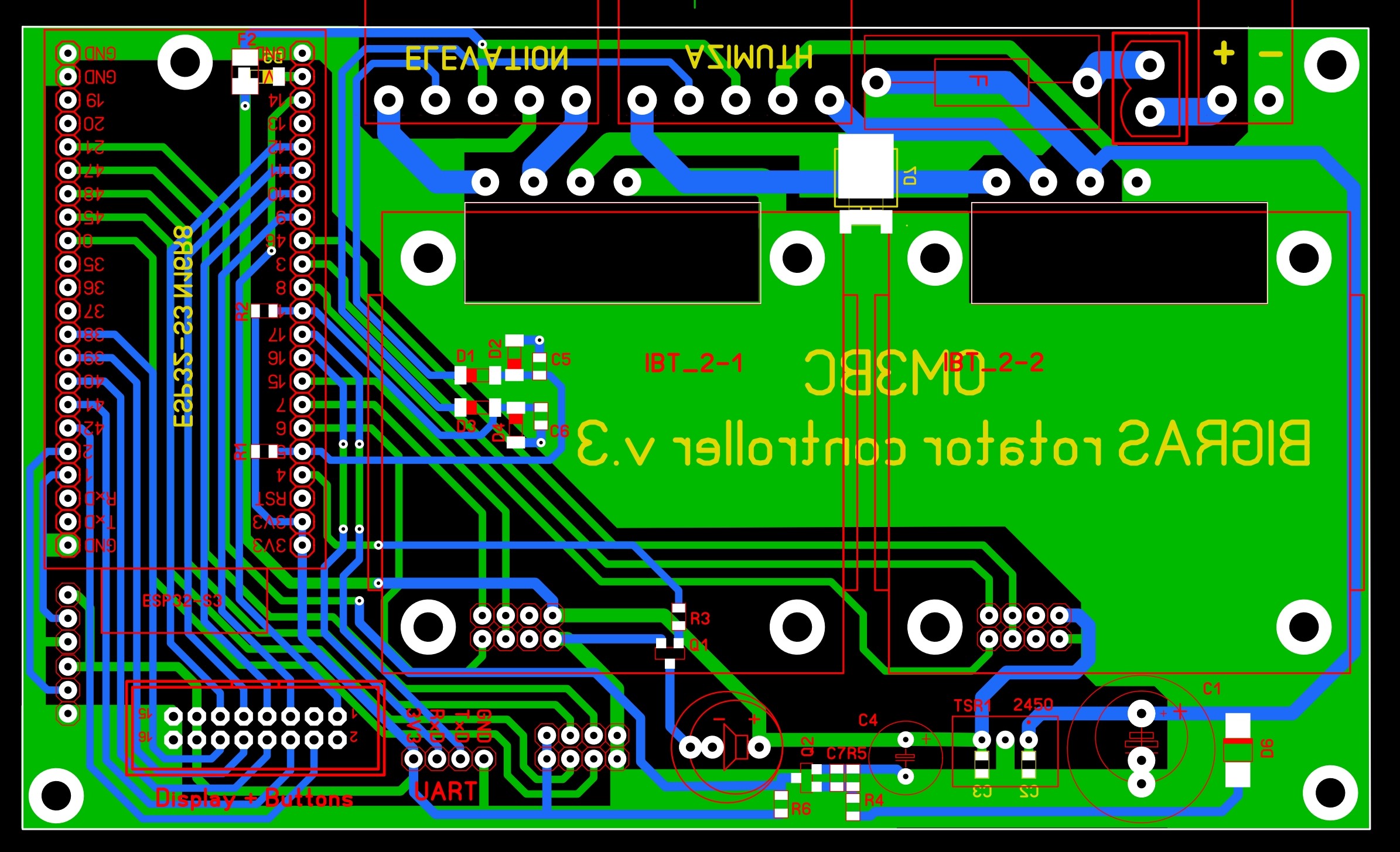
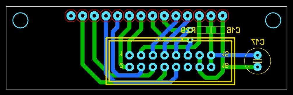
As you can see the PCB is quite simple. It contains only some parts and the connectors. There should be no major problem with the acquisition of the parts either, because the value of each resistor is 10 k, and the ceramic capacitors are 100 nF. Their size is 0805. Except for the zener and protection diodes, all diodes are shottky.
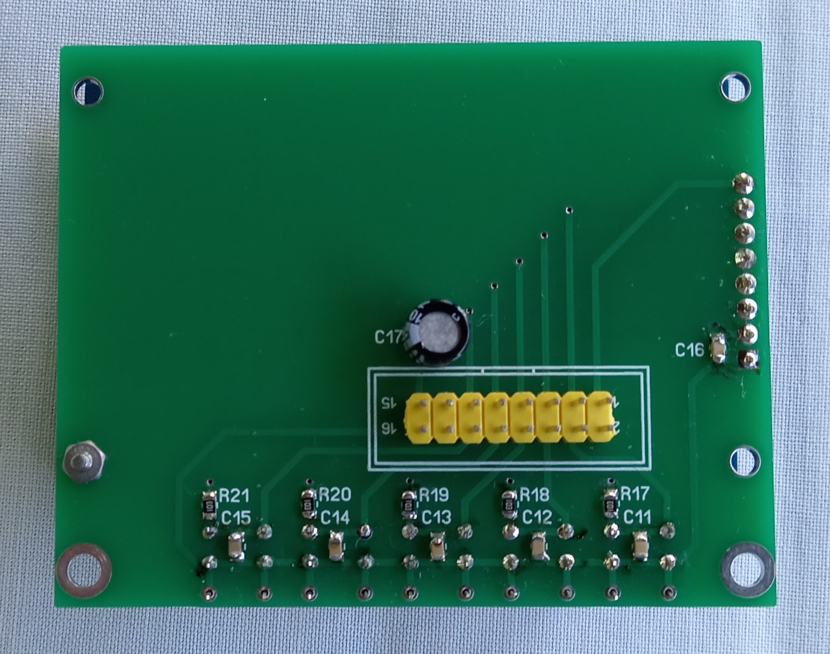
The display and push buttons have been placed on a separate panel.
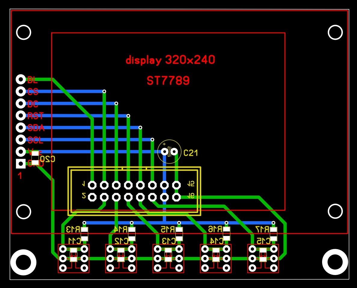
Each display size has its own panel. The 1.9-inch display panel has 5.8x5.8 mm buttons, while the 2.4 and 2.8-inch displays have 8.5x8.5 mm buttons.
The following gerber files can be used for the production of PCB panels:
logic, 1.9display, 2.4display, 2.8display
Since the WiFi antenna is located on the module, make sure the controller is either installed in a plastic box, or the metal box is not too closed so that the WiFi signal gets out of the box. Due to cooling needs, the box should not be too closed anyway.
Box made with a 3D printer for the controller with 1.9 , 2.4 , 2.8 inch display.
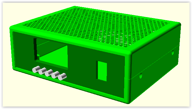
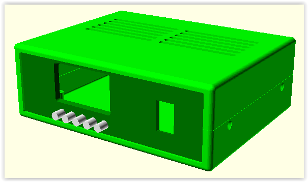
lid_xxh lid_xxv
The power supply is not part of the controller. As a power supply unit, choose a type that can withstand sudden changes in current consumption. I use a 24V 10A power supply used for LEDs. I adjusted its voltage below 20V with the help of the trimmer included (to the minimum that can be set). The value of the D6 diode is critical. A Zener diode must be used that, when turned off, the ESP32 - 21 port (interrupt) goes to the LOG0 state in time so that the processor has enough time to save the current position, but the voltage fluctuation that occurs when starting the motors (the current can be as high as 10A) does not activate the interrupt. This largely depends on the quality of the power supply.
Installation:
If you already have experience using micropython and the ESP module, you should fill the content of the program package into the module in the way you are used to.
If you have no experience or are using the ESP32 module for the first time, follow the instructions below.
1. download program Thonny to the operating system (I recommend using Windows).
2. create an arbitrary directory where you copy the following file firmware
Extract the contents of the firmware package to a new directory, e.g. ROTOR.
Connect the ESP module to the computer with a USB cable. In the Windows system, check the port number assigned to the ESP in the "Device Manager" menu. If the system does not recognize the module, install the following driver CH343SER.
First option:
Windows:
open the install_upython.bat file
correct the port number (python3 must be installed)
save the file
run the bat file
Linux:
run the sh file: bash install_upython.sh
Second option:
Download the programot to load uPython and the uPython
When we start the loading program, a window like this appears:

Here, select ESP-S3 in the first row:
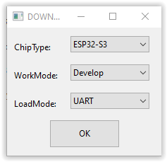
Pressing OK brings up the program itself:
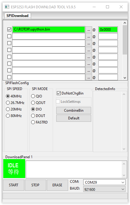
Use the ... button to load the bin file, set the COM port number to the one the ESP received. The first step is to erase the contents of the ESP memory with the ERASE button. When it's done with that (it will take a while), load uPython into ESP by pressing the START button. If this operation was also successful, we are already over the most difficult parts.
Now we can start Thonny. In the Tools - Options menu, set the following:
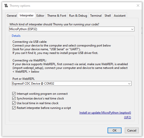
Of course, in the second option, the port number of our own module must be entered.
In the View menu, select Files. After that a simplified file manager appears on the left side. In the upper half, enter the directory where the firmware can be found. The files in the upper window should be copied one by one to the lower window (right click - Upload to /). Make sure that the fonts in the fonts directory needs to be included in the fonts directory on ESP too. With the right-click Upload to /, the entire font library can be copied at once.
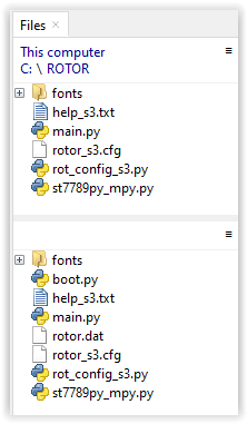
This operation completes the installation of the firmware. Unfortunately, it has happened to me that the content of the file was corrupted during copying. If the icon shown in the picture is not displayed next to the name of the file, the copying must be repeated. You will not have the "rotor.dat" file yet. It is created only after the controller is turned on.
partlist
A version for a 4-inch touchscreen display has also been prepared:
The above instructions are also valid for this version. The difference is that the touch sensor driver must also be installed (ft6x36.py). The firmware is not compatible with the old one, so the files in firmware_96.zip must be installed in the ESP32. The method of connecting the control panel and the display can be found in connector.txt. Since there are no buttons, a separate panel is not required for the display, it is enough to connect the pins of the connectors properly, or create an intermediate board based on the image below. For quick adjustment, a potentiometer(s) can also be used in this version. If there is elevation control, then by touching the center of the azimuth circle, the potentiometer position will be displayed instead of the azimuth and elevation. The current position of the azimuth potentiometer is also shown by the point outside the azimuth circle. By touching the azimuth field, the antenna turns to the position specified by the azimuth potentiometer. If the elevation field is touched, the elevation turns to the direction specified by the potentiometer. If the rotator is used for horizontal rotation only, the current position of the potentiometer is permanently visible in the elevation field. In this case, this field must be touched to rotate the antenna in the desired direction. If we do not use a potentiometer, the point outside the azimuth circle shows the position given by the external command (where the antenna should turn).
If you prefer push buttons (or have a display without a touch sensor), or if radio frequency interferes with the touch display (unfortunately, capacitive sensors are prone to this), you can also use it with push buttons. For this type, you can use this PCB:
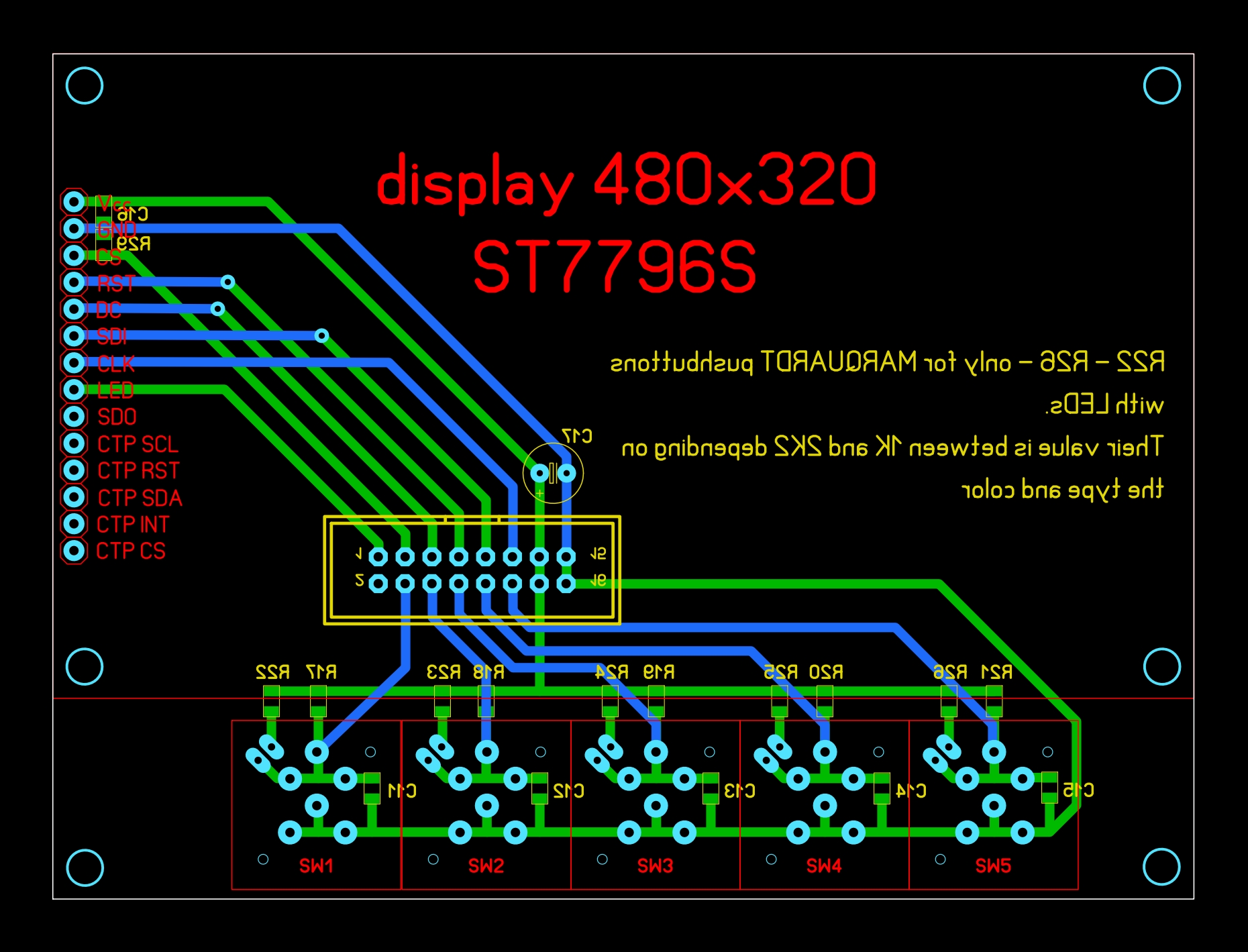
Here are MARQUARDT type push buttons are used. These are much more pleasant to operate, they react gently and reliably. We can also use buttons with or without LED.
gerber file for making the PCB: display40
Universal firmware this can be used for push button and touch sensor displays.
Options for purchasing parts:
ESP32 module
Motorcontroller
UART-COM level converter
1.9" display
2.4" display
2.8" display
4.0" display
stabilizer
switches
beeper
single row female conector
ribbon cable connector
socket header connector
main switch 15x21
power supply or here
green connectors or here
or
PV05-5.08-H-P EUROCLAMP
PV02-5.08-H-P EUROCLAMP
PV02-5.08-V-P EUROCLAMP
SH05-5.08 EUROCLAMP
SH02-5.08 EUROCLAMP
MARQUARDT Square Key Cap Round
A satellite tracking program was also created to control the antenna, which can be found at this address. With this program, it is possible to automatically track several satellites.
The drawings and the program in the processor are the intellectual property of the author. Its commercial use is only permitted with the written consent of the author!