The controller is primarily designed for BIGRAS rotators, but can also
be used for other rotators using pulse feedback. By disabling vertical
rotation, it is also possible to fully use RAK or BIGRAK rotators. With
a small modification of the firmware, it can also be used with analog
feedback (YAESU). This controller can be used with a 4" display. It is
important that the display has an ST7796 type chip and the touch sensor
is capacitive with an FT6336 chip.
Available functions:
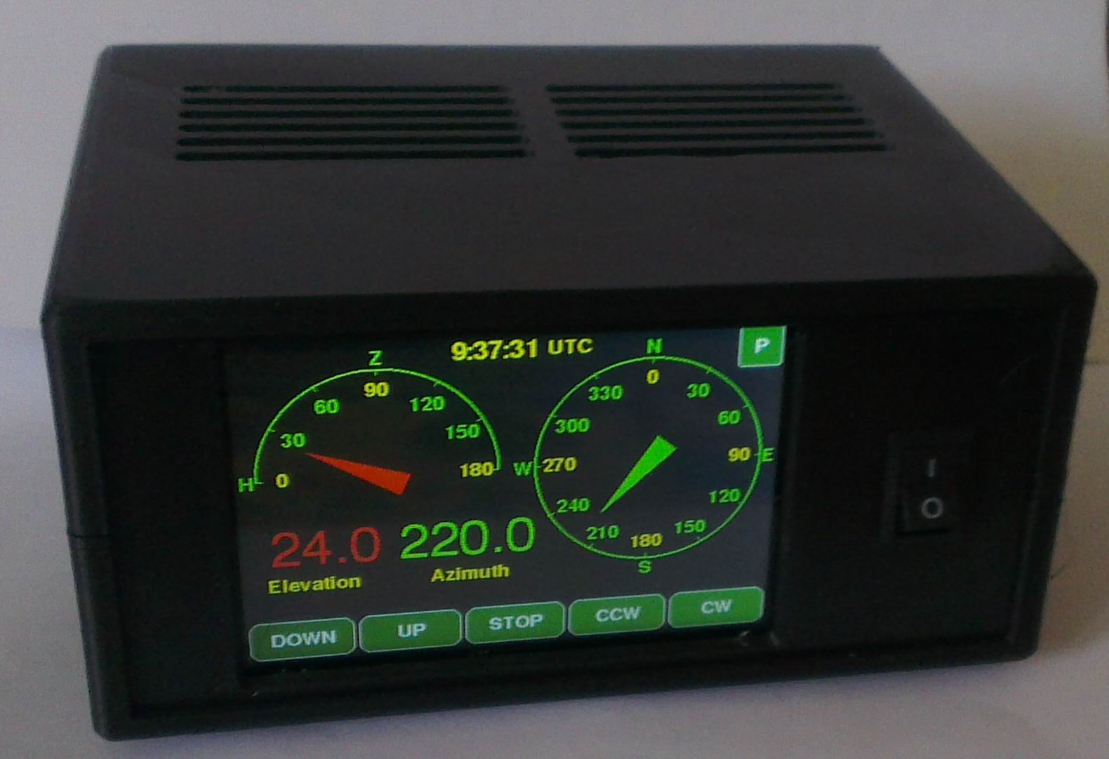
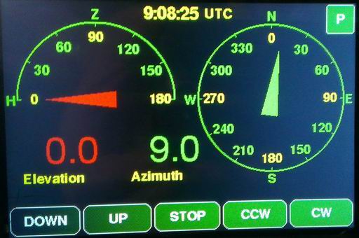
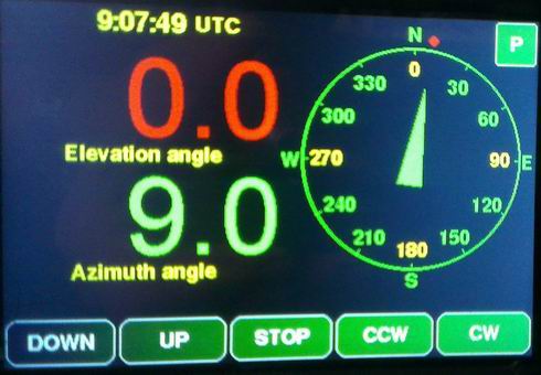
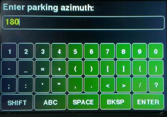
The controller can be controlled in four ways. Of the two USB connectors on the board, one is a native USB 1.1 type, its speed is 12 Mbps. The other USB port is a USB-UART converter. Bd. In addition, a standard RS232 COM port can be used via a TTL-RS232 converter. Their speed can be adjusted between 300 and 230400 Bd. With the appropriate program, it is possible to control the antenna via WiFi as well. The mentioned options can even be used simultaneously. The settings are also accessible either directly from the controller via the serial port, or through WiFi, in which case we can change the settings by opening the appropriate web page. The main commands of the controller are compatible with the Yaesu GS232, so it should be selected if necessary. The full command set can be accessed via the serial port with the H command. In addition to Yaesu commands, it can also interpret FOXDELTA type commands and standard NMEA type GPGGA messages. If we have previously set our own coordinates, it calculates the azimuth and elevation of the given point based on the data in the messages, and then rotates the antenna in the direction of the given point. This function is mainly used when tracking high-altitude balloons (for example, the program called SondeMonitor has such an output, so this program can rotate the antenna directly). The controller can also emulate the PSTRotator and rotctld programs. If one of the programs we use, the control of the rotor is only possible with the PSTRotator or rotctl protocol (e.g. SatDump, Horus), we only need to set the appropriate port number in both places, and the IP address of the controller in the program we use, which we can see in the upper left corner of the Menu window. Of course, it is necessary to be connected to the WiFi network. The menu is accessed by pressing and holding the STOP button (until the menu window appears). Here, we can scroll by pressing (or holding down) the up and down buttons. After that, we can select the value in the selected line with the right-hand buttons. After pressing the SET button, for parameters where it appears, the value can be entered on the appearing keyboard. The Background parameter allows us to choose from several color combinations. Since the controller is suitable for several types of rotators, the data showed on the display also differs depending on whether there is elevation or not, and whether we prefer large numbers that are easier to see from afar or graphics and smaller numbers.
Description:
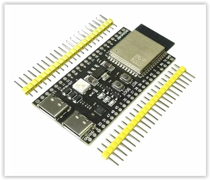
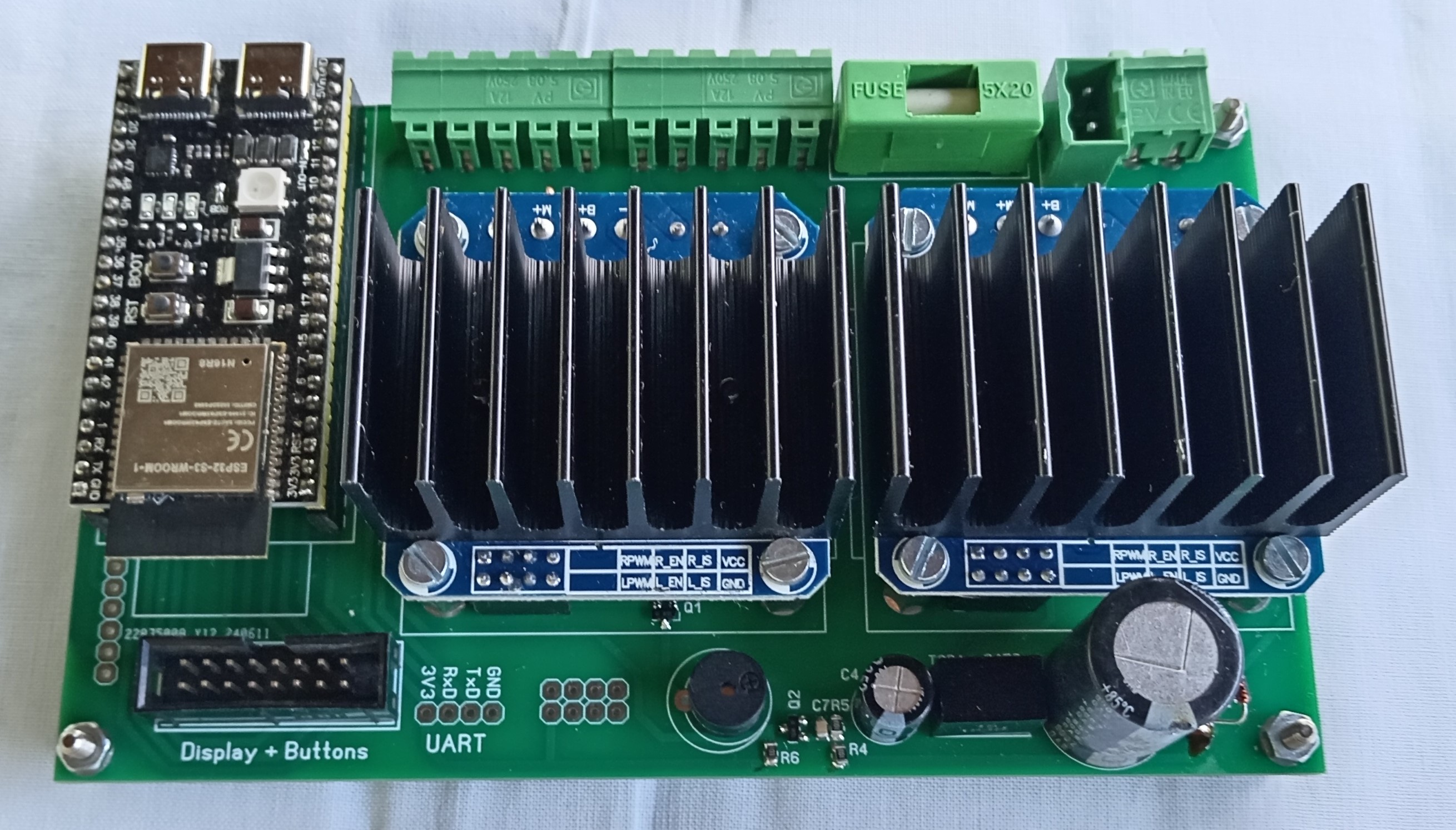
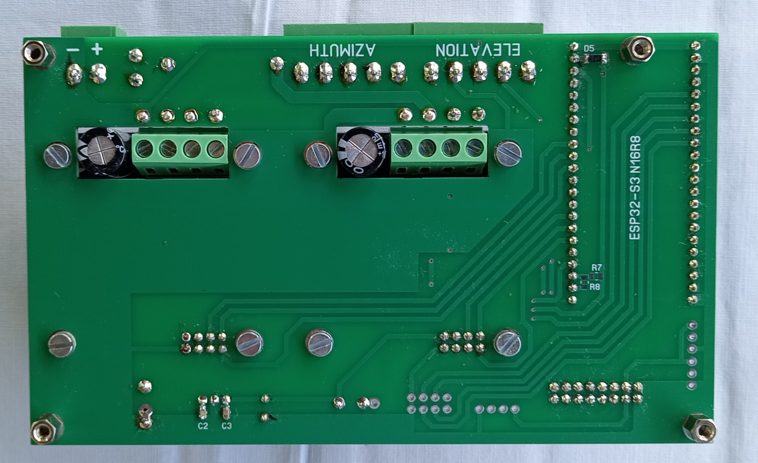
The central element of the control circuit is an ESP32-S3 N16R8 type module. We need to purchase the module shown in the picture because there is also a version on the market in which the push buttons are directly above the USB connectors. However, that module is 2.54 mm narrower, so it will not fit into the PCB due to the location of the pin rows.
 OR
OR 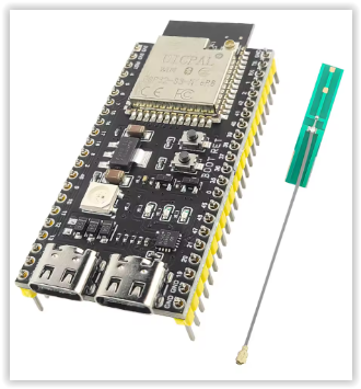
Some manufacturers sell the module with a loaded demo program, which flashes the LED on the module after switching it on. If you have managed to obtain one, you need to open the RGB short circuit on the module. Next to the RGB LED there is another short circuit with label IN-OUT. This must be shorted! In order to simplify the preparation, a ready-made module, IBT_2 type was used to control the motor itself. Since the COM connections are already being phased out, it would not have been reasonable to integrate this on the printed circuit board, but if necessary, this module can also be connected separately. There are 5 push buttons on the display. Their function depends on the current situation. The function of which push button is used is indicated on the push button. If both horizontal and vertical rotation are active, then from left to right: antenna down, antenna up, stop or menu, antenna left (counterclockwise), antenna right (clockwise).
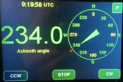
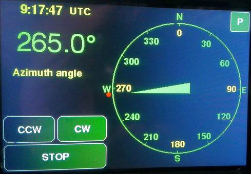
If only horizontal rotation is active, the leftmost button is for turning left, the rightmost button is for turning right, and the middle button is for stopping or menu.
The STOP button has several functions. Pressing it briefly stops the motors. If you hold it down for a little longer, a BLOCK label will appear. In this case, external commands are blocked, the rotor only responds to the buttons. This is indicated by a three-time beep. If you hold the STOP button down for a long time, you will enter the menu.
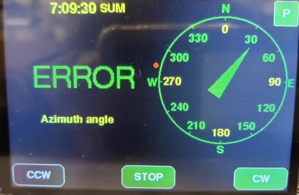
If the rotor gets stuck or cannot rotate for other reasons, after 5 seconds an ERROR message will appear and the rotor will stop to protect the motors from overload. If an external command is received in this case, it will beep 3 times to indicate that it cannot execute the command. We can exit this state by pressing the STOP button.
The functions described below are for convenience only and do not affect the main functions of the controller. Their installation is not necessary:
The P1 and P2 potentiometers make it easier to turn the antenna to the desired position by setting the desired direction with the potentiometer and then pressing the appropriate area on display (see below) and the antenna will be set to the direction specified by the potentiometer. We can use a common potentiometer for the horizontal and vertical directions, or separate potentiometers for the horizontal and vertical directions.
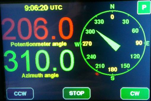
If a potentiometer is used, the red dot outside the azimuth circle indicates the direction of the potentiometer. If a display is set that does not show the potentiometer position numerically, touching the center of the azimuth circle will show the position of the potentiometers. The antenna can be turned in the direction indicated by the potentiometer by touching the area on the display where the azimuth or elevation value is written.
By tapping the P button in the upper right corner, the antenna will rotate in the direction set by the Parking azimuth and Parking elevation parameters.
The main commands used to rotate the antenna are:
Waaa eee - turn the antenna horizontally to the aaa direction, vertically to the eee direction
A - azimuth stop
AZ=aaa - turn the antenna horizontally to the aaa direction
AZ=aaa EL=eee - turn the antenna horizontally to the aaa direction, vertically to the eee direction
E - elevation stop
EL=eee - turn the antenna vertically to the eee direction
S - all stop
Maaa - turn the antenna horizontally to the aaa direction
Keee - turn the antenna vertically to the eee direction
ML - turn the antenna counterclockwise
MR - turn the antenna clockwise
MU - turn the antenna up
MD - turn the antenna down
L - turn the antenna counterclockwise
R - turn the antenna clockwise
U - turn the antenna up
D - turn the antenna down
C - current position of the antenna in the horizontal direction
C2 - current position of the antenna in the horizontal and vertical directions
B - current position of the antenna in the vertical direction
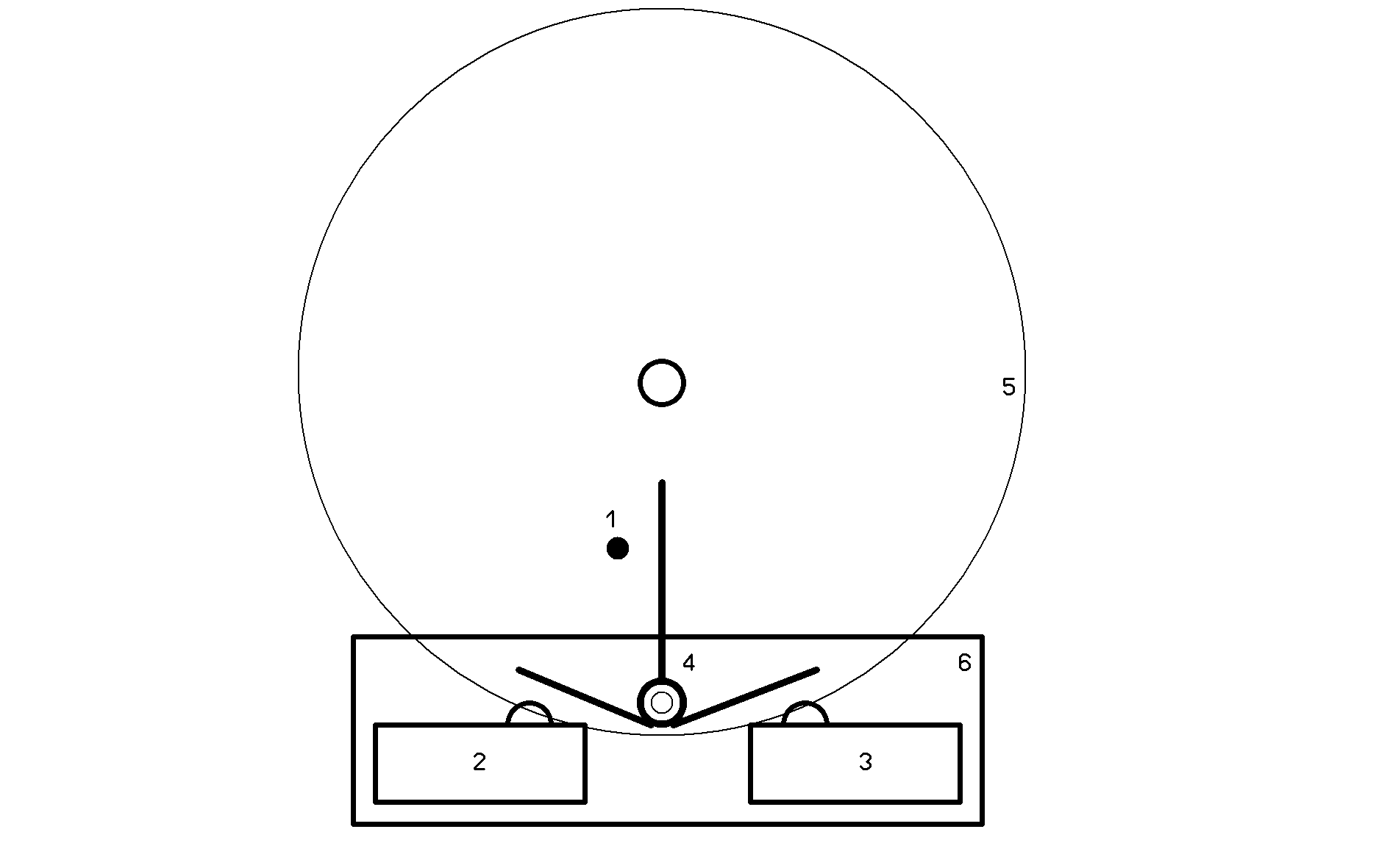
In order for the antenna calibration to work properly, a limit switch must be built into the rotator mechanism, which stops the rotation in the horizontal direction at the starting position. Such a limit switch is originally built in the vertical direction, but in the horizontal direction - for reasons that are incomprehensible to me - it is not, so we have to include it. I guess no one would like their coaxial cable to break because it got wrapped around the antenna. This is not too difficult to solve, but it requires a little creativity based on what tools and limit switches are available to each person. In any case, you have to make sure that the switch is only active in one direction. This picture illustrates a possible solution. Here:
1 - vertical rod on the gear
2,3 - limit switches
4 - lever made of sheet metal for switching the limit switches
5 - gear
6 - auxiliary panel on which the lever shaft and the limit switches are mounted
The advantage of this solution is that there is a limit switch in both directions, and by properly adjusting the plate lever, the required overshoot can be achieved. The antenna should be fixed on the rotor so that the overshoot is the same at both ends. In this case, the value of the overshoot in the counterclockwise direction is entered in the menu as the "azimuth offset" value.
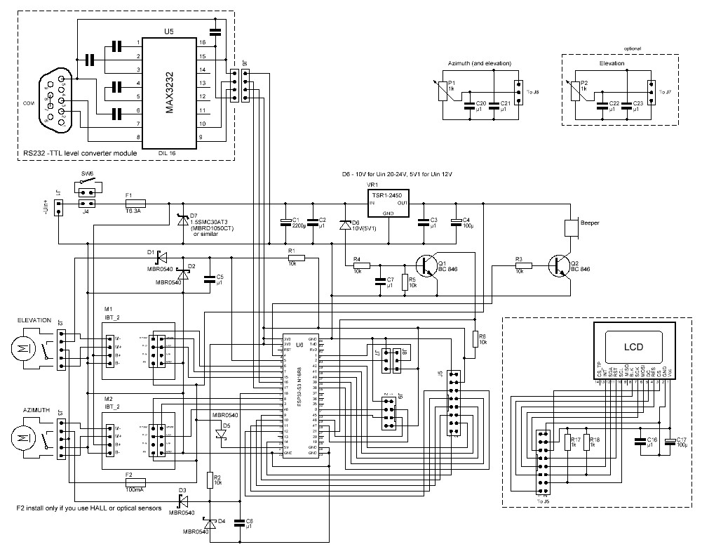
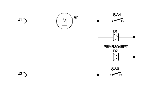
The wiring diagram:
Settings:
The most important parameters can be accessed in the menu. This can be accessed by long pressing the middle button (STOP). In this case, a multi-line menu appears in which you can scroll (UP, DOWN) to reach the appropriate menu item. These are the following:
AZ turn to: here we can set where the antenna should turn horizontally when we exit the menu
EL turn to: here we can set where the antenna should turn vertically when we exit the menu
Pulse/degree: here we can set how many pulses the rotor gives for 1 degree of rotation
Azimuth offset: how many degrees the antenna zero point is from the left end position
Elevation offset: how many degrees the horizontal position is from the limit switch
Max. azimuth: the antenna position in the upper end position
Max. elevation: the maximum allowed elevation for the given antenna system (90 or 180 degrees)
Beeper type: if the value is OFF, the beeper is turned off, it does not give a sound signal when a command is received on the serial port, DC - in case of active beeper, or a number that means the frequency of the beeper. Its value can be between 200 and 5000.
Elevation: ON or OFF, if the rotor is not suitable for vertical rotation, set this parameter to OFF
Overturn: ON or OFF, if the antenna allows overturning, then by setting this parameter to ON, the rotor can be used continuously in the horizontal direction between the offset and the value set with max. azimuth. In OFF state only between 0 and 360.
Autoturn: In ON state if the CW, CCW, UP or DOWN button is pressed for 5 seconds, then after the button is released the antenna will continue to rotate until either one of the buttons is pressed again or the rotor reaches the end position
Zero point: this parameter determines where the mechanical zero point of the rotator is, this can be in the south or north direction
WiFi: how WiFi should behave when starting. We can turn it off or set it to try to connect to the WiFi network when starting. If this fails, switch to AP mode.
Backlight: backlight intensity
COM baudrate: serial port speed
Degree size: position font size
Screensaver: screensaver, in case of 0 it is off (the display is constantly lit), in case of number, after this number of seconds the display turns off
Orientation: display orientation. This allows us to set whether the main switch on the front panel is on the right or left side.
Minimal turn: The minimum rotation speed of the rotor at which the antenna still rotates reliably. When starting, it accelerates from this speed to the maximum speed, and before stopping, it slows down to this speed so that the rotor is not affected by strong impacts. This is why the movement is more continuous even when tracking a satellite.
Background: color combinations used on the display
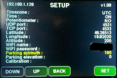
Timezone: set your own time zone if you do not want to see time in UTC. (Time difference between UTC and winter time. Daylight saving time is set automatically)
Time: ON or OFF, depending on whether you want to see the clock or not.
Potentiometer: set whether there is a potentiometer and if so, is it common for both directions or separate
UDP port: set the port for PSTRotator
TCP port: set the port for rotctl
Latitude: set your own latitude coordinate
Longitude: set your own longitude coordinate
Altitude: set your own altitude above sea level
WiFi name: set your own WiFi AP name
WiFi password: set your own WiFi password
Parking azimuth: set the parking position (if you want to use it)
Parking elevation: set the parking position (if you want to use it)
Calibrate calibrate the position of the rotator. In the horizontal direction, it can only be used with the subsequent installation of limit switches, in the vertical direction the limit switch is already installed
If the WiFi SSID and password are set correctly, then after restarting, we will see the IP address obtained in the upper left corner of the menu window. We can access the settings via a browser at this IP address. The firmware version number is shown in the upper right corner. In case of successful connection, if the time display is enabled in the menu, the exact time will be displayed in UTC or local time at the top of the display, depending on the time zone set in the menu.
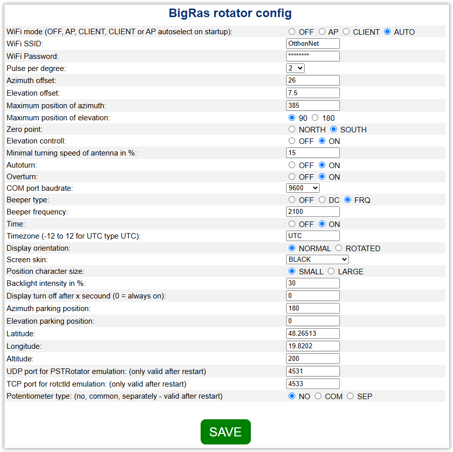
If you want to use WiFi, make sure to check in the menu whether WiFi is OFF. If so, turn it on. Select whether you want AP only, CLIENT only, or switch to AP+Client mode. If the controller cannot connect to the WiFi network, and if this function is not disabled, it will create an AP, which can be accessed either with the ROTOR-AP SSID or the 192.168.4.1 IP address. In this case, the password is 1234567890. If you have set WiFi, you must restart the controller, because it only checks the settings when you turn it on.
The third way to set parameters is to send the appropriate commands over the serial port. The list of commands can be retrieved with the H or h command.
Preparation:
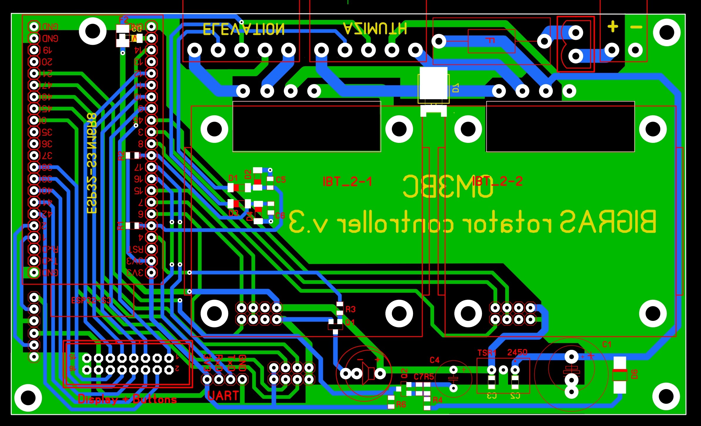
As you can see, the PCB is quite simple. It only contains a few components and connectors. There should be no major problems with purchasing the components either, because all resistors are 10 kΩ, and the ceramic capacitors are 100 nF. All are 0805 in size. Except for the zener and protection diodes, all diodes are shottky.
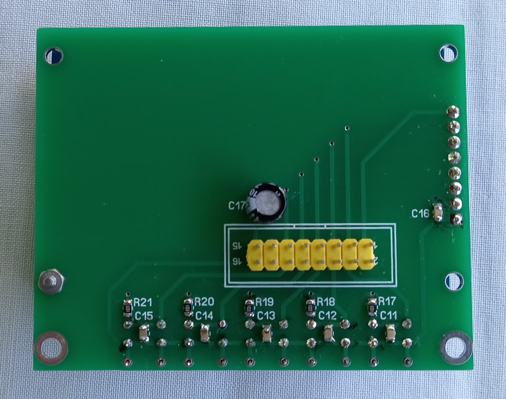
The display can also be connected directly, by attaching the 16-pin connector to one end of the ribbon cable and a single-row connector to the other end, which is connected according to the diagram. Alternatively, you can use an intermediate panel like this:
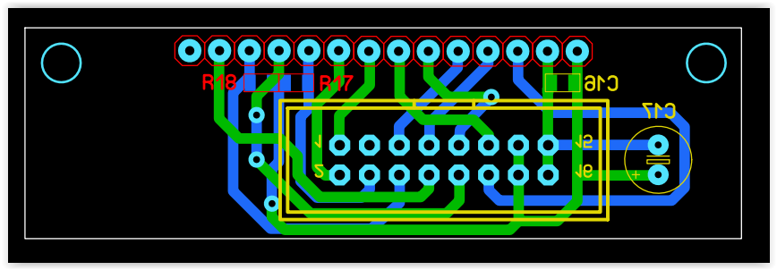
gerber file
Since the WiFi antenna is located on the module, make sure to either mount the controller in a plastic box or the metal box is not too closed so that the WiFi signal can escape from the box. In any case, the box should not be too closed for cooling reasons.
A 3D printed box for the controller is available here.

The power supply is not part of the controller. Choose a type of power supply that can withstand sudden changes in current consumption. I use a 24V 10A power supply used for LEDs. I set its voltage to a value below 20V (the minimum that can be set) using the trimmer inside. The value of the D6 diode is critical. A correct type of Zener diode must be used where, when turned off, the ESP32 - 21 port (interrupt) goes to the LOG0 state in time so that the processor has enough time to save the current position, but the voltage fluctuation that occurs when starting the motors (current consumption can be up to 10A) does not activate the interrupt. This largely depends on the quality of the power supply.
Installation:
The installation is very simple. You just need to run the appropriate bat file. The entire package is called rotator.zip (version 1.22). This zip file must be unpacked into a folder of your choice. The first time you use it, you should always use the install_with_factory_reset.bat file. First, connect the ESP panel to the computer. In the device manager, check what COM number the panel received. Open the aforementioned bat for edit, set the COM number, and correct the path to the python program. If python3 is in the PATH, then just write python at the beginning of the line. Save it, then run it. After that, you just have to wait for the bat to run. This takes a while, sometimes it seems like nothing is happening, but it does work in the background, so be patient. If the bat has run and the standard "Press a button..." message appears, then the installation is complete. If any other error message appears, it is likely that you entered the wrong COM number or there is a problem with python. To upgrade the firmware install_upgrade.bat should be run to keep the settings. The COM number and python path needs to be edited in this file as well.
partlist
Options for purchasing parts:
ESP32 module or ESP32S3-IPEX
Motorcontroller
UART-COM level converter
4.0" display
stabilizer
beeper
single row female conector
ribbon cable connector
socket header connector
main switch 15x21
powersubbly or here
green connectors or here
or
PV05-5.08-H-P EUROCLAMP
PV02-5.08-H-P EUROCLAMP
PV02-5.08-V-P EUROCLAMP
SH05-5.08 EUROCLAMP
SH02-5.08 EUROCLAMP
The drawings and the program in the processor are the intellectual property of the author. Its commercial use is only permitted with the written consent of the author!
A satellite tracking program was also created to control the antenna, which can be found at this address. With this program, it is possible to automatically track several satellites.