We may witness the times when the number of ham radio operators are decreasing, since in the age of computers and smartphones the youngsters are not charmed by amateur radio hobby. It is possible to arouse their attention only with special activities. Such an ocassion may be launching balloons filled with helium, carrying a radio transmitter. This kind of operation is not so expensive nowadays and unites the technical activity with radio communication and helps to understand the background of certain meteorological phenomena. To save time of fellow hobbyists and to help develop the necessary equipment, I have designed a radio transmitter described as follows.
The useful payload has been built in three versions:
1. For the 144 MHz amateur radio band, uses FM modulation and sends data packets according to APRS recommendations,
2. for the 434 MHz band, uses FSK modulation and transmits RTTY signals, conform to the UKHAS practice, or standards,
3. for the 434 MHz band, the same as the previous variant, but a ready made radio module was used, so its construction is simpler.
Each type may be fed using a 1.5V battery (Litium-based ones are the best) or by a rechargeable 1.2V power source which can be kept charged by a solar cell. The operating time of this payload using a RAVER LITHIUM Model L6/2B battery is 50 hours. In case of solar cell fed rechargeable battery, operating time is theoretically endless assuming the solar cell and the battery is operating properly. The working conditions of this device controlled by a microprocessor. This part initialize, set and control the parameters of the radio transmitter (frequency, power, deviation), reads data from the GPS receiver, interprets them and transforms them into the necessary format, measures the temperature and voltages, possibly the air pressure. According to given parameters it sorts the data and makes the radio transmitter to keep sending it at preprogrammed intervals. When a transmission period ends, the processor put the radio transmitter, gps receiver in a power save mode and switches its own clock signal to 500 kHz. The equipment waits in this power save state until the next operating period. If there is no solar cell then the first payload version waits as long as we have chosen with the HOLD OFF command. The 2. and 3. version pips twice in every minute to indicate correct function and helps to make the frequency corrections. If the payload is powered from an accumulator and a solar cell, then based on the parts of the day during daytime it transmits in intervals set with HOLD OFF and during night it doubles the interval. Version 2 and 3 also extends the interval of the pips.
Description and settings of the different versions
For the setting of the parameters in this units, we need a terminal access on a serial line. For this we'll need a level converter which will convert the TTL signal to RS232 and a terminal program (like Hyperterminal).
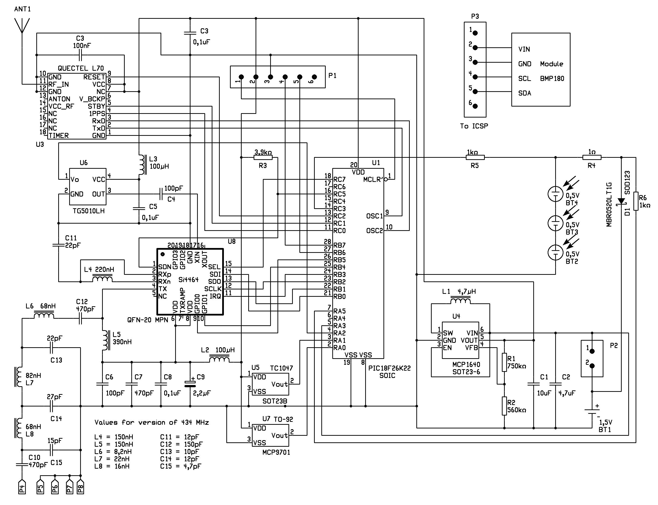
Figure 1. Connection diagram of version 1. and 2.
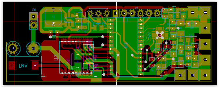
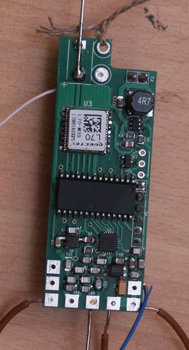
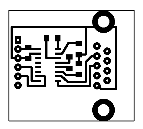
Figure 2. PCB view of version 1 and 2
Version 1
Description
This version works in the 144 MHz amateur radio band using FM modulation and sends APRS data packets. These packets are coded according to MIC-E protocoll and compressed for the shortest transmission time. In these condensed packets there are data about geographical position, height, speed and direction of flight. A so called tail text may be added to these data. This is a plain text which may contain further information such as temperature, voltage, current or air pressure.
Using CWID ON command, this equipment will send its callsign in Morse code also. The advantage of this method is that there is no need for any kind of additional equipment, other than our ears and the „onboard computer” between them. It's mainly worth to switch on this „broadcast mode” in case we intend to search for the landed payload by direction finding. However, this is not strictly necessary, because if the balloon has already exceeded the 1500 meter altitude and during the descent the height goes below 300 meters, a so-called search mode is turned on. In this mode, the equipment is not broadcasting normal packets, but CW morse signals at about 50 words / minute speed. This broadcast contains the callsign and the geographical position as a 10-digit QTH locator, which is in a few meters of accuracy, so it's sufficient to find it. Then follows a broadcast of protocol AX25 UI package, which contains the coordinates in unencrypted format.
Another form of balloon flight is, that only sufficient gas is filled into the balloon to be stabilized at a few thousand meters above the ground. It is worth to use solar cells and batteries to keep the equipment operational for a longer time. You will not have to worry if the balloon flies too far away, because the processor will set the frequency used in the current area based on it's coordinates. Another possibility is to turn on RTTY transmission with the RTTY ON command. The frequency of the RTTY transmission can be set with RFRQ. The default setting is 144,600 MHz. The RTTY text consists of the time, coordinates, height, internal temperature, battery voltage as well as solar cell voltage and charging current of the rechargable battery if the solar cell is also used.
In the 144 MHz band, the antenna size is already significant. You can use the classic GP antenna made of thinner wires (the driven element is to be connected to point P4 and counterweights are to be connected to points P5, P6, P7, P8) or a J antenna. I decided to use a modified J-antenna as it can be seen on the drawing.
3. kép J-antenna 144,8 MHz-re
The 1. and 2. segment is a 300ohm flat television cable and the 3. segment is a 0.4mm diameter copper wire. For the GPS antenna, we can use either a JTI_Antenna-1575AT43A40_2006-09 chip antenna or a 47mm long 0.7mm diameter wire.
Settings:
First connect the payload with the TTL-RS232 converter (pay attention to the correct orientation) and start the terminal program, with the transmission rate set to 9600 8N1. Now when you turn on the payload, you should see the following message: "BALLOON PAYLOAD V 5.0 BY OM3BC." If you wait 5 seconds, the device goes in normal operating mode. If you press the SPACE or ENTER button within 5 seconds after the appearance of the first text, then we get into command mode. In this case, the "Type Help for Info" and "cmd>" text is displayed.
If you issue the help command, the following text appears:
Commands (with example):
DISP - Display all setings
TAIL (tail text every n)-(on,off,n)-n=0 is off and 1<n<9 every n-th message
TTEXT - tail text - 250 chars max
CALIBRATE Calibrate 1200Hz
MYCall - (mycall OM3BC-11)
TRace - (xmit/off) for debugging only
TXDelay - txdelay n 0<n<100 (n x 10 ms)
TXTail - TX tail time (n x 10 ms)
UNProto - (unproto aprs v wide1-1) - 3 digis max
SYMBOL - 2 APRS symbols - default is BALLOON (/O)
FRQ - frequency in Hz
RFRQ - frequency for RTTY in Hz
RTTY - ON or OFF
OFFSET - modem frequency offset in Hz (max. +-30000)
DEV - deviation in Hz
BAUD - baudrate for RTTY transmitting
DBITS - number of databits
SBITS - number of stopbits 1.5 = 15
POWER or POUT - output power in mW
REF - XO or TCXO frequency in Hz (min. 10000000, max. 32000000
UBLOX - ON = UBLOX, OFF = QUECTEL
PRESSure - ON = BMP180 present, OFF = not present
HOLDoff - hold off time in minutes
CWID - send CW identifier ON or OFF
CWSP or IDSP - speed of CW identifier in WPM
SOLARcell - mounted - ON or not mounted - OFF
ECHO - ON or OFF
SLEEP - switch the GPS receiver - ON or OFF
SERGPS - baudrate of GPS receiver (4800 or 9600 or 19200)
DATA - identification of radio chip
VER - software version
EXIT - end of command interpreter
Tail text commands:
\U - send batery voltage
\V - send system voltage
\S - send solar voltage
\I - send solar current
\T - send internal temperature
\X - send external temperature
\W - send radiochip temperature
\P - send pressure
\F - send temperature from pressure sensor
\B - send number of received satellites
\Z - software version
OK
cmd>
It's enough to type in the part written with capital letters.
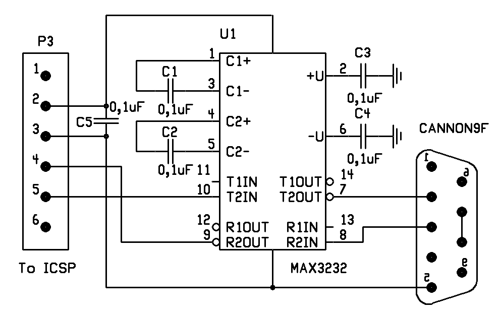
Figure 4 Connection diagram of the level converter
Now look at what do these commands mean.
MYCall - This is the call sign of the payload-radio. Since in this case we work in the frequency-band reserved for radio amateurs, a valid amateur radio callsign must be included. Since it's a flying device, according to APRS convention, the hyphen must be followed by number 11.
UNProto - It is not necessary to rewrite the text because it will not be transmitted in this format. During the MIC-E coding is will be rewritten. In this case, the BC means om3BC, PL means payload and 50 is the software version.
FRQ - This is the station frequency in Hz. The 144.800 MHz frequency is assigned to the APRS network throughout Europe. (and throughout IARU Region 1)
RFRQ - This is the station frequency for sending RTTY messages in Hz. The default frequency is 144.250 MHz.
RTTY - Switch RTTY message transmit on or off.
OFFSET - the difference between the sub-carrier and the main carrier used in RTTY. This is used to set the receiver in case the nominal frequency of the received signal fits in the passband of the receiver
DEV - deviation of RTTY signal (frequency difference between "MARK" and "SPACE")
BAUD - Baud rate of RTTY signal
DBITS - number of data bits
SBITS - number of stop bits
POWER OUT - The radio output power in milliwatts, can be between 1 and 100. The output value is only relative, the real value is highly dependent on the supply voltage and the actual circuit type as well.
CWSP - The Morse code transmission speed, word / minute, where the keyword is PARIS.
CWID - The transmission of the Morse code identification switched on or off.
TCXO FREQUENCY- TCXO reference oscillator frequency. For this version a VCTCXO type oscillator must be used, where the term refers to a voltage-controlled temperature-compensated crystal-oscillator. The purchase of these oscillators is not an easy task, but the frequency can be any value between 10 and 32 MHz (30 MHz is good to have around) to ease up the situation a bit. In my case, this value is 19.2 MHz. The value of the oscillator can be given in Hz accuracy and this command is used for calibration too. Because the real frequency is rarely the same as that indicated on the frame, we have to adjust this value. It's a simple case when we have a frequency counter and we can measure the frequency accurately. In this case, we enter the measured value using the command. Worse case is if we're unable to measure the reference frequency. In this case, all that remains is a "trial and error" method when we are trying until the output frequency is exactly 144.8 MHz (plus or minus 100 to 200 Hz does not play a major role). If you enter a new value, the unit must be switched off and on again because the new value is read only during initialization.
TXDelay - Time that elapses between switching to transmission and sending the data. This is necessary for the receiving station to detect the signal and switch to reception. The time is to be given in 10 ms increments. During this time, synchronization bytes are transmitted.
TXTail - Similar as in the previous case, it means the number of synchronization bytes at the end of the broadcast. This informs the receiving station about the end of the package.
SYMBOL - This sets what symbol is used on the www.aprs.fi website for your radio. /O is used for balloons, but you can choose a different one from this symbol_table.
HOLD off - The time between transmitted packets in minutes. Transmission is done the following way. The processor is waiting in hibernated state for the HOLD off time to pass. Then the processor switches to a higher speed, wakes up the payload from the hibernation, reads the GPS coordinates. It assembles the packet based on the setting, attaches the TailText if set, then transmits the packet. Then it waits for 20 seconds and repeats the steps. After that it hibernates itself again for the HOLD off duration.
TRace - Used for testing. If set to ON, the assembled packets won't be transmitted over the radio, only over the COM port. We can check wether the correct text will be transmitted or we need to change some settings.
ECHO - When set to ON, the payload will send back the character received over the COM port. This way we can check if the payload is responding to the data received over the COM port.
SOLAR - This is to set if there is a solar cell attached to the payload or the payload is working only from a battery.
UBLOX - Fortunately the frame of the GPS receivers L70 from QUECTEL and the MAX6C, MAX7C, MAX8C from UBLOX are the same so any of them can be used for the payload, but their internal scheme is a bit different and they need to be set up differently. We can tell the processor which receiver is used with this command. If set to ON the receiver is from UBLOX, if set to OFF it is from QUECTEL.
PRESSURE - This tells the processor whether a type BMP180 barometer is attached to the payload
SLEEP- With this we can override the hibernating function. It can be useful if we use a different GPS receiver or for some reasons it's waking up too slowly. In these cases it might be worthwhile to leave it awake even with the increased power consumption.
SERGPS - The communication speed between the GPS receiver and the device.
CALIBRATE - We can check the modulation on the A.2 port of the processor with this command. Experience tells there is no need for calibration.
DATA - Gives back the version of the radio. After mounting the components we need to check with this command whether the processor can detect the processor. If it gives back only 1s then we need to fix the mounting of the radio chip. The correct mounting of the radio chips is the hardest part in the building process.
TAIL - This parameter sets if we want to attach the text set in the TTEXT to the end of the packet. If yes, then in what prevalence.
TTEXT - Is used to set the attached text, also used for the telemetric data. The combination of the following parameters can be used:
\U - voltage of the battery or rechargable battery
\V - voltage of the operating BUS (processor, GPS receiver, radio)
\S - voltage of the solar cell
\I - charging current of the rechargable battery
\T - internal temperature
\X - external temperature (if the MCP9700 sensor is outside of the insulating wrapping)
\W - temperature of the radio chip
\P - air pressure if the BMP180 is attached
\F - air temperature measured by the BMP180
\B - the number of received GPS sattelites
\Z - version of the firmware
During the initial setup we might need some additional help. TEST1 and TEST2 commands are for this purpose.After sending the TEST1 command, we should see a significant change in current on the battery every 5 seconds. This shows if the device is alternating between hibernated and active state. This test can be turned off with button E when in the active state.TEST2 command is used to check the correct communication between the GPS receiver and the processor. The device will always send us the actual value. We can change it by U (up) or D (down). In normal room temperature using button D we need to find the first speed value where the transmission starts to make mistakes. Then using button U we have to find the value where it starts to make mistakes again. Then we need to set the device to the average of these two values ( (lower+upper)/2 ). We can save this value to the memory with S (save) or exit without saving with E.
To find out what the parameters are actually set to, you can enter the command DISP (not case-sensitive). A similar text is obtained:
cmd>disp
MYCall OM3BC-11
UNProto BCPL50 V WIDE1-1 V WIDE2-2
FREQUENCY: 144800000 Hz
RTTY FREQUENCY: 144600000 Hz
DEVIATION: 850 Hz
SPEED: 100 Bd
DATA BITS: 7
STOP BITS: 2
MODEM OFFSET: 1200 Hz
POWER OUT: 50 mW
CWSP: 20 WPM
CWID OFF
TCXO FREQUENCY: 19200037 Hz
TXDelay 26
TXTail 2
SYMBOL /O
HOLD off 3
TRace OFF
ECHO ON
SOLAR OFF
UBLOX OFF
PRESSURE OFF
SLEEP ON
RTTY ON
SERGPS 9600 Bd
TAIL Every 2
TTEXT BCTRACK v.\Z - Ubat= \uV, Usol= \sV Isol= \imA T1= \tC P= \phPa
OK
cmd>
Version 2 and 3
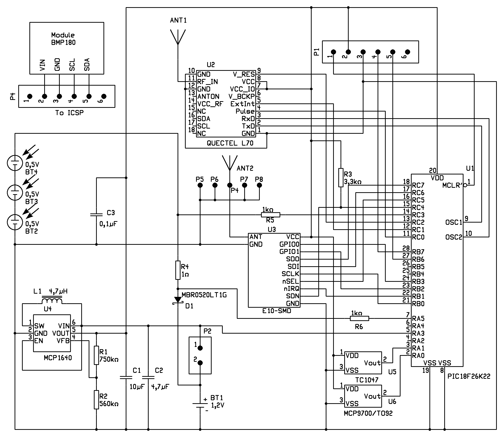
Figure 5. Connection diagram of version 3
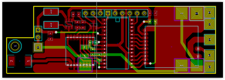
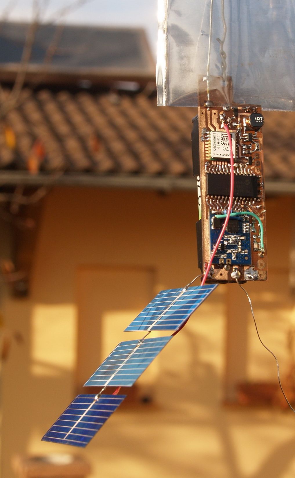
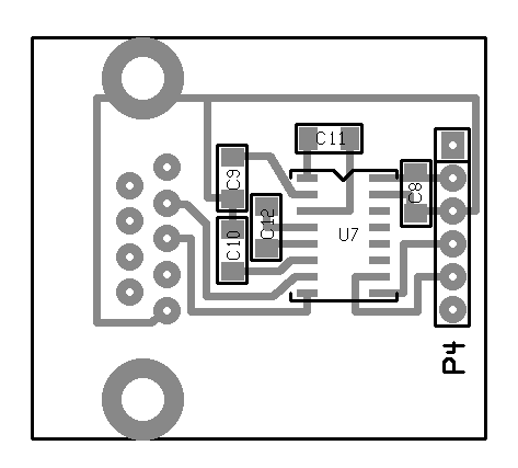
Figure 6. PCB view of version 3
Circuit discription
These versions operate in the 430 MHz band, and use FSK modulation. The broadcasted text follows the recommendation of UKHAS and is transmitted in RTTY mode. The transmission cycle is the following: The processor revives then reads the current coordinates from the GPS receiver, measures the temperatures, voltages, possibly the air pressure based on the set parameters. If it is set to in the options, it sends the necessary data in Morse code. Waits for two seconds then generates the text and sends it in RTTY mode. Waits for two seconds again and repeats text. If the current height is more than 5000 meters, the processor measures the battery voltage. If this voltage is greater than 1.2V, then it doubles the output power and repeats the transmission. This increased power increases the chance of the transmission to be received at greater distances. If the transmission is completed, the unit will enter hibernation mode.
With these versions our job with of the antennas is easier, because it's enough to use five thin piece of wire (best is to split a steel cable so we get tinned steel wires) with length of 17,5cm. The first one is connected to the connection point P4, it will hang downwards. Then comes the four counterweight which points to the left, forward, backward and to the right. For the GPS antenna the same solution can be chosen as in the first version.
Settings
As far as the functions and settings go, both versions are equivalent. Only difference is that, while the second version is put together using transmitter components, the third version uses a ready-made radio module. This makes rebuilding a lot easier although it has its drawbacks.
The structure of text is the following:
$$BC04S,10,09:45:59,4815.9080,01949.1967,195.8,17.9,1.40,1.79,118*42
1 2 3 4 5 6 7 8 9 10 11 19
Constant content:
1 – sychronizing signals
2 – identifier
3 – serial/sentence number or the number of received satellites
4 – time in UTC (Universal Time Coordinated)
5 – geographical latitude
6 – geographical longitude
7 – height (above sea level)
19 – checksum
Optional content:
8 – air pressure
9 – speed
10 – direction
11 – internal temperature
12 – temperature of the radio chip
13 – external temperature
14 – system voltage
15 – battery or rechargable battery voltage
16 – solar cell voltage
17 – charging current of the rechargable battery
18 – QTH locator (6 or 10 character)
Only those optional data appears in the text whose parametization was allowed. In this example, they are:
8 – internal temperature
9 – battery voltage
10 – solar cell voltage
11 – charging current
* marks the end of the text, after which the checksum follows.
The same TTL-RS232 converter and program is used as in the first version. The way to get to the command mode is also the same. The help content and the used commands are a little different as a result of the different mode:
Meaning of each command:
DISP - display all setings
CALL - identifier for payload
CWCALL - CW identifier
FRQ - frequency in Hz
POWER or POUT - output power in mW
REF - XO or TCXO frequency in Hz (min. 10000000, max. 33000000
TCXO - YES = TCXO, NO = XO
OFFSET - modem frequency offset in Hz (max. +-30000)
DEV - deviation in Hz
BAUD - baudrate for RTTY transmitting
DBITS - number of databits
SBITS - number of stopbits 1.5 = 15
IDSP or CWSP - speed of CW identifier in WPM
CWID - send CW identifier YES or NO
CWBAT - send batery voltage in CW - YES or NO
CWL - send QRA loc. and altitude in CW - YES or NO
COURSE - send course and speed - YES or NO
BATV - send batery voltage - YES or NO
SUPV - send supply voltage - YES or NO
PRESS - pressure sensor mounted - YES or NO and send pressure
SOLAR - solarcell mounted YES or NO
USOL - send solar voltage - YES or NO
ISOL - send solar current YES or NO
UBLOX - ON = UBLOX OFF = QUECTEL
TEMP - send inbox temperature - YES or NO
INTEMP - send radiochip temperature - YES or NO
EXTEMP - send external temperature - YES or NO
LOCATOR- send QRA locator - YES or NO
LOC10 - send 10 char. of QRA loc. ON = 10, OFF = 6 charakters
SENT - send ON = sentence / OFF = visible satelites
SLEEP - switch the GPS receiver to hybernate mode - YES or NO
SERGPS - baudrate of GPS receiver (4800 or 9600 or 19200)
TUNE - set the Xtal frequency
DATA - identification of radio chip
VER - software version
EXIT - end of command interpreter
OK
cmd>
Meaning of each command:
DISP - to display the set parameters
CALL - ID of the payload
CWCALL - ID of the payload in case of Morse code
FRQ - used frequency
POWER - output power 1 - 100 mW
REF - frequency of the reference oscillator
TCXO - determines whether a temperature-compensated oscillator or a crystal is connected to the radio
OFFSET - the difference between the sub-carrier and the main carrier used in RTTY. This is used to set the receiver in case the nominal frequency of the received signal fits in the passband of the receiver
DEV - deviation of RTTY signal (frequency difference between "MARK" and "SPACE")
BAUD - Baud rate of RTTY signal
DBITS - number of data bits
SBITS - number of stop bits
IDSP or CWSP - speed of the Morse code
CWID - enables Morse code transmission
CWBAT - enables sending of battery voltage by Morse code
CWL - enables sending of QTH-locator by Morse code
COURSE - enables sending speed and direction
BATV - enables sending the battery voltage
SUPV - enables sending the voltage of system bus
PRESS - enables sending the air pressure
SOLAR - solar panel is connected
USOL - enables sending the voltage of solar cell
ISOL - enables sending the charging current
UBLOX - GPS type used: ON = UBLOX, OFF = QUECTEL
TEMP - enables sending the PCB tempretaure mesured by sensor
INTEMP - enables sending the tempereature of rado chip
EXTEMP - enables sending the temperature of outer MCP9700 heat sensor
LOCATOR - enables sending the QTH locator
LOC10 - enables sending the ten character QTH locator
SENT - ON = sending of the broadcast number, OFF = sending the number of received satellites
SLEEP - transition into hibernated state, or not
SERGPS - speed of the GPS-receiver port
TUNE - tuning of crystal oscillator – ineffective in case of TCXO
DATA - version number of the radio chip - After mounting the components we can check if the processor detects the radio
VER - version number of the firmware
EXIT - to quit the command mode
Recommended parameters:
UBLOX OFF
SOLARcell OFF
TEMPerature ON
INternalTEMPerature OFF
speed & COURSE OFF
BATVoltage ON
SUPplyVoltage OFF
SolarVoltage ON
SolarCurrent ON
SENTence OFF
CWID ON
CWBAT ON
CWTEMP ON
LOCATOR OFF
LOC10 OFF
CWLOC OFF
PRESSure ON
SLEEP ON
CALL: BC05S
CWCALL: BCPL5
FREQUENCY: 434900000 Hz
DEVIATION: 870 Hz
SPEED: 100 Bd
DATA BITS: 7
STOP BITS: 2
POWER OUT: 50 mW
CWID speed: 20 WPM
MODEM OFFSET: 1200 Hz
TCXO FREQUENCY: 19200006 Hz
SERGPS 9600 Bd
OK
cmd>
Summary
The E10 SMD-type radio, as well as the BMP180 modules are available on the Internet at reasonable prices. The radio module in addition to its simplicity has a major drawback, which is that it has no TCXO component, but just a simple crystal. For this reason the frequency of the radio is highly dependent on the ambient temperature. When the balloon climbs up to a few thousand meters, the ambient temperature falls well below zero degree, so the accuracy and stability of the broadcast frequency approaches a barrier that can hardly be tolerated (or even goes well over that). This can be improved with good insulation, which in turn increases the total weight, or perhaps with the use of a TCXO crystal but this is a job for clock-makers. I tried DRF4463 and RFM26W modules also.
Unfortunately, the result was always the same. That's why I chose the hard way and assembled the first and second versions using normal radio components. It also allows you to use the PCB for both amateur bands by changing the output filter components. In case of the third version if you won't use a solar cell, you can use a single-sided board, the other side contains only parts needed for the solar panel.
The software placed in the processor and the drawing documentation is intellectual property of the author. Business utilization is possible only on the basis of the author's prior written consent.
Connection diagram of version 1. and 2.
Connection diagram of version 3
Connection diagram of the adapter
PCB - ver. 1. és 2. front side, back side
PCB - ver. 3. front side, back side
PCB - TTL-RS232 level converter
Silk Snap - ver. 1. és 2. felső oldal-pdf, alsó oldal-pdf, png
Silk Snap - ver. 3. front side-pdf, back side-pdf, png
Silk Snap - TTL-RS232 level converter
Firmware ver. 1
Firmware ver. 2
Firmware ver. 3
New version of firmware
After the continued development, a new firmware was created which combines the first and the second version of the program. With this verion, the desired message can be transmitted both in the RTTY and APRS modes. The new DISP and HELP commands are the following:
cmd>disp
MYCall OM3BC-11
TCXO FREQUENCY: 19200007 Hz
POWER OUT: 100 mW
RTTY: ON
RTTY FREQUENCY: 144600000 Hz
DEVIATION: 850 Hz
SPEED: 100 Bd
DATA BITS: 7
STOP BITS: 2
MODEM OFFSET: 1200 Hz
BATVoltage: OFF
SUPplyVoltage: OFF
TEMPerature: OFF
INternalTEMPerature: OFF
EXternalTEMPerature: OFF
CWID: ON
CW FREQUENCY: 144600000 Hz
CWSP: 20 WPM
CWLOC: OFF
CWBAT: OFF
CWTEMP: OFF
LOCATOR: ON
LOC10: ON
APRS: ON
APRS FREQUENCY: 144800000 Hz
UNProto BCPL55 V WIDE1-1 V WIDE2-2
TXDelay: 26
TXTail: 2
SYMBOL: /O
TRace: OFF
TAIL: Every 2
TTEXT: BCTRACK v.\Z - Ubat= \uV, T1= \TC
HOLDOFF: 2
ECHO: ON
SOLAR: OFF
UBLOX: OFF
PRESSURE: OFF
SLEEP: ON
SERGPS: 9600 Bd
GPS: OFF
OK
cmd>
cmd>help
Commands (with example):
DISP - Display all setings
MYCall - (mycall OM3BC-11)
TRace - (xmit/off) for debugging only
TXDelay - txdelay n 0<n<100 (n x 10 ms)
TXTail - TX tail time (n x 10 ms)
UNProto - (unproto aprs v wide1-1) - 3 digis max
SYMBOL - 2 APRS symbols - default is BALLOON (/O)
FRQ - frequency for APRS in Hz
RFRQ - frequency for RTTY in Hz
RTTY - ON or OFF
APRS - ON or OFF
OFFSET - modem frequency offset in Hz (max. +-30000)
DEV - deviation in Hz
BAUD - baudrate for RTTY transmitting
DBITS - number of databits
SBITS - number of stopbits 1.5 = 15
BATV - send batery voltage (RTTY) - YES or NO
SUPV - send supply voltage (RTTY) - YES or NO
TEMP - send inbox temperature (RTTY) - YES or NO
INTEMP - send radiochip temperature (RTTY) - YES or NO
EXTEMP - send external temperature (RTTY) - YES or NO
POUT - output power in mW
REF - XO or TCXO frequency in Hz (min. 10000000, max. 32000000
UBLOX - ON = UBLOX, OFF = QUECTEL
PRESSure - ON = BMP180 present, OFF = not present
HOLDoff - hold off time in minutes
CWID - send CW identifier ON or OFF
CWBAT - send batery voltage (CW) - YES or NO
CWTEMP - send temperature (CW) - YES or NO
CWSP - speed of CW identifier in WPM
CWL - send QRA loc. and altitude in CW - YES or NO
LOCATOR - send QRA locator - YES or NO
LOC10 - send 10 char. of QRA loc. ON = 10, OFF = 6 charakters
SOLARcell - mounted - ON or not mounted - OFF
USOL - send solar voltage - YES or NO
ISOL - send solar current YES or NO
ECHO - ON or OFF
SLEEP - switch the GPS receiver - ON or OFF
SERGPS - baudrate of GPS receiver (4800 or 9600 or 19200)
CALIBRATE - calibrate 1200Hz
DATA - identification of radio chip
GPS - ON - for normal mode, OFF - for testing without GPS receiver
VER - software version
EXIT - end of command interpreter
TAIL (tail text every n)-(on,off,n)-n=0 is off and 1<n<9 every n-th message
TTEXT - tail text - 250 chars max
Tail text commands:
\U - send batery voltage
\V - send system voltage
\S - send solar voltage
\I - send solar current
\T - send internal temperature
\X - send external temperature
\W - send radiochip temperature
\P - send pressure
\F - send temperature from pressure sensor
\B - send number of received satellites
\Z - software version
OK
cmd>
The commands are the same as before. A new command is GPS ON/OFF. This is used for testing purposes. If we turn off the GPS with the GPS OFF command, the program won't wait for the message from the GPS receiver, but replaces it with a test one. With this we can test the set parameters in a convenient fashion.