APRS repeater using
PIC18F26K22 MCU
Foreword:
Internet
has been sweeping almost everything away, so we thought the age of packet radio
was over. Fortunately Bob Bruninga WB4APR saw it differently, and he developed
the APRS protocol at the end of the eighties. APRS stands for Automatic
Position Reporting System. The name of the protocol suggests this system is
used for communicating our geographical position only. However, the APRS
protocol is much more complex and is useful for many purposes. With the help of
this protocol in addition to our position we can send meteorological information,
telemetric data, and personal messages and above all, it can help in case of
emergency or provide information about several useful activities. The base of
the whole system is the AX.25 (packet radio) protocol. In this case only UI
frames are used. The APRS system is not a network. It is not necessary to build
up routes, and because only UI frames are used, it is not necessary to log in to
a network. It is enough to send out our information, and in case we are in the vicinity
of an APRS digipeater then the system completes all tasks when receiving our
packets.
The whole
system can be divided into three parts:
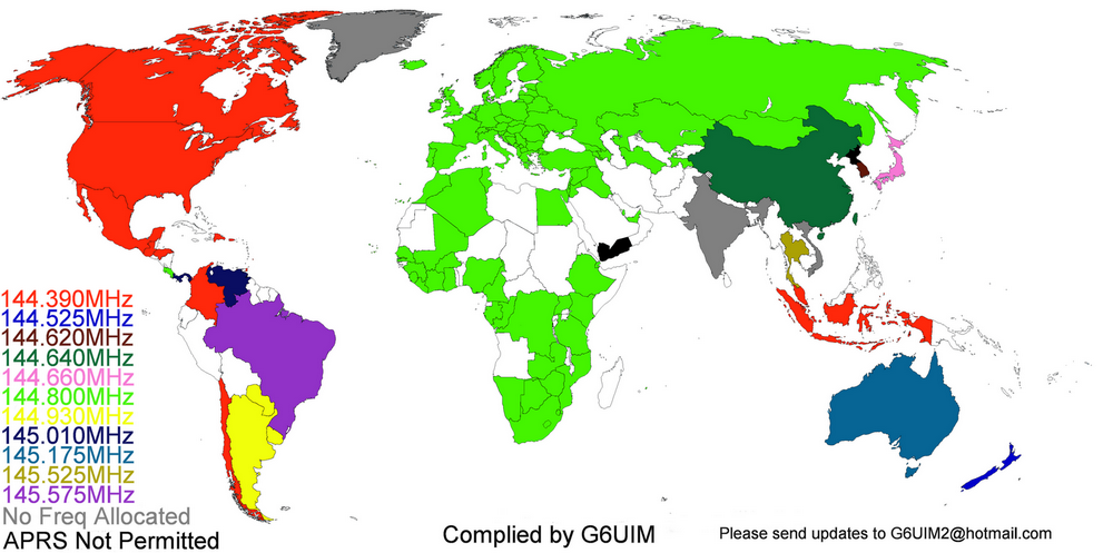
Because in
Europe the 144.800 MHz frequency was chosen for the APRS system, there is no
need for additional frequency coordination.
Hardware:
In
connection with the digipeater I built around the PIC16F867A processor, I have received
several feedbacks that its reception was good only with a clear and very
high-quality input signal. Everybody wished for the return of the good old
TCM3105. I decided to give another chance for that modem IC. That is why I have
designed a completely new degipeater. Since the decoding of the audio signal is
carried out by the modem IC, the accurate timing in the processor was not
important. This allowed me the comfort of not having to write the software in
assembler. The advantage of this is also that it was not difficult to implement
new functions, but unfortunately there was not enough room for it in the PIC16F876A.
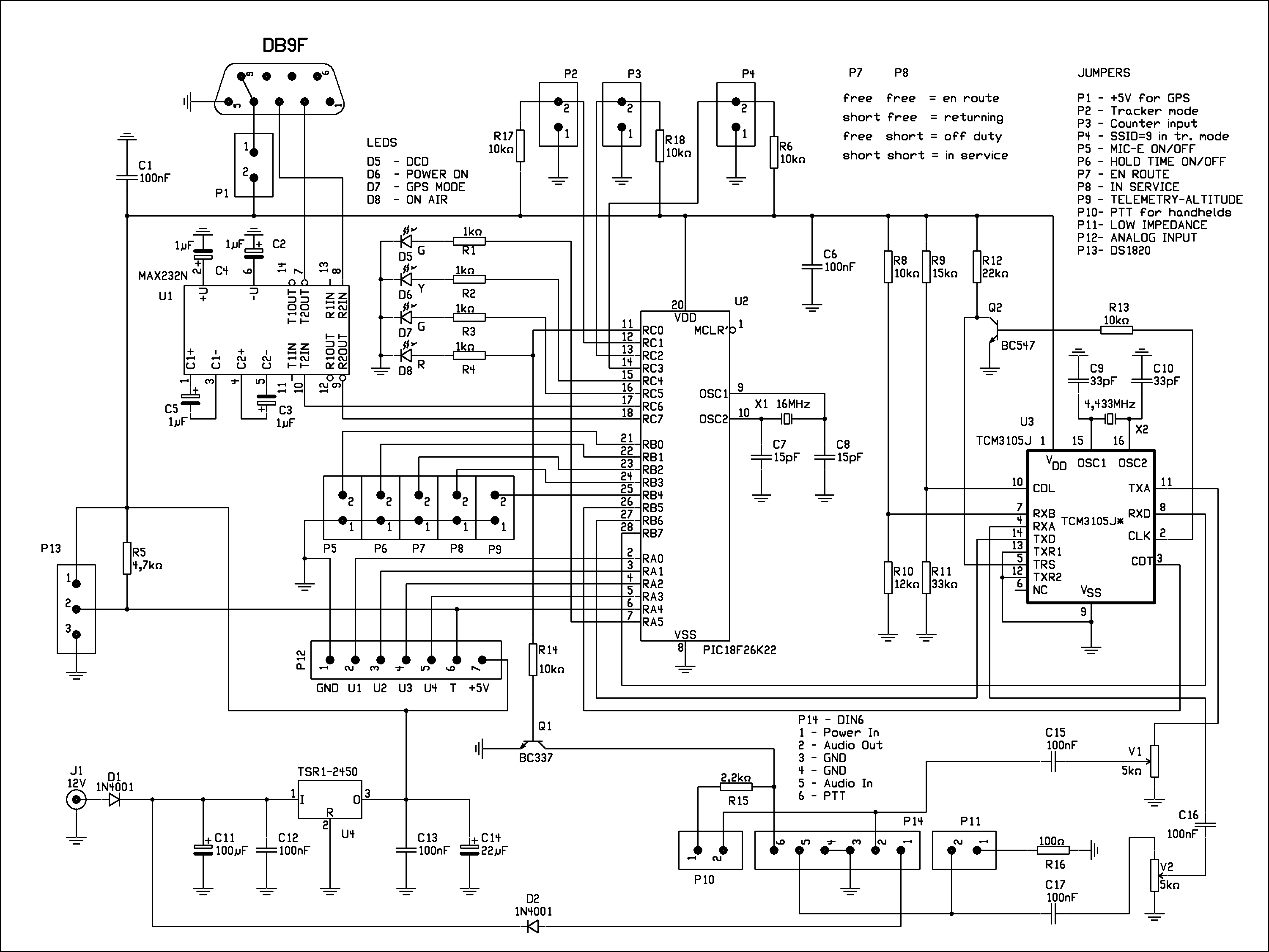
I have chosen the PIC18F26K22 because it has the largest memory among the 28-pin
MCUs and its price is acceptable as well. Since microcontrollers these days
integrate many peripherals, the whole equipment requires only 3 ICs (plus
voltage regulator), 2 crystals, 5 connectors and some passive components
altogether. The used voltage regulator may be a bit overkill here, but it can
provide 1 A of current without cooling. Who has enough room may use a linear
regulator, but if a GPS receiver is also connected, one needs to use a rather
large heat sink (which is not suitable for a battery powered portable mode of
operation). As the 28-pin IC has been chosen because of its memory size, some free
inputs remained, which may be used to change configuration parameters.
The
functions of the jumpers are:
That let
the program have enough time for each task, inner PLL is switched on in the processor,
and like the 10 MHz crystal reports a 40 MHz clock rate.
Software:
The
software consists of several main functional parts.
Monitor
Example
If TAIL 5
then
!4815.91N/01949.21Ey
BCDIGI v.2.2 Qth Filakovo
!4815.91N/01949.21Ey
BCDIGI v.2.2 Qth Filakovo
!4815.91N/01949.21Ey
BCDIGI v.2.2 Qth Filakovo
!4815.91N/01949.21Ey
BCDIGI v.2.2 Qth Filakovo
!4815.91N/01949.21EyPHG32304/A=000577
BCDIGI v.2.2 APRS Repeater with PIC18F26K22 – http://www.om3bc.com
The
frequency of BTEXT 1 BEACON EVERY n, repetition of BTEXT 2 may be chosen by
TAIL EVERY n command. In the first case n means time in minutes, the value may
be 0 and
The commands t, s, h, l, and a
are only valid for the temperature sensor connected to the P13
connector. The T1, T2, T3, T4, and T5 values always show the actual
temperature. The unit of
the temperature (Celsius or Fahrenheit) can be selected by TEMP C or
TEMP F
command. The unit is transmitted after the temperature value. In case
of
measuring supply voltage, a voltage divider must be used to prevent the
MCU
input from getting higher voltage than 4 V.
The \r
command displays the time elapsed since the last start of the TNC. The \f command inserts the value of
the counter into beacon text. The input of this counter is the P3
connector and the appearing value is the half of the number of impulses
sent to it. This input is first of all appropriate to measure the
number of turns of fans used in PCs where the appearing value is equal to the turns per minute of that fan. Connections: Black is GND, red 12V, yellow P3 pin 2. The
voltage & temperature value sent in beacon text is completely independent of those described
in telemetry part.
The APRS
system rules are applicable for the beacon text format APRS.
Calibrate
If you don’t disable the repeater using DIGIpeat OFF command, then it will
operate in both tracker and telemetry mode.
0 4 11 24 50 80
256 200 120 60 30 20 10 sec
The two LEDs on the right
of the serial port socket show if there is a connection with the GPS receiver.
If the CRC of received data is correct then the upper LED lights up. When the
GPS receiver has found our actual position (it may take some time according to
the receiver) than the lower LED lights up as well, showing everything is all
right with the GPS receiver and the equipment is ready to pass along our
geographical position. Naturally till this state does not set in, the tracker
does not send any kind of data through the radio. If the tracker is not used in
a car, we may choose another symbol from the
table of the graphical symbols,
which is to be written among the parameters. By jumpers P7 and P8 we can choose
what we are doing right now even during drive or walk. (Only in MIC-E mode.)
Four possibilities can be chosen by these two jumpers:
When the jumper is in default position (open) it means en route, because this is the most often used situation.
It is necessary to grant these
parameters, when setting up the program or you may choose from these
opportunities as follows:
FILTER
ON/OFF - when ON, only the printable characters are sent to the serial port
ECHO ON/OFF - when ON, sends back the received characters on
the serial port
TEMP C/F – the unit of the temperature measurement
TXDelay – the time between activation of PTT and the sending of the first data – actually
the number of FLAGs sent before each packet
PERSistence
- the watching of a busy channel.
TXTail - the time between the
last data and deactivating PTT – the number of FLAGs sent after each packet – the
smallest possible value is 2
GPS $GPRMC/$GPGGA/$GPGLL which raw packet is to be sent in tracker mode
TRace RCV/XMIT/OFF – tracking mode for testing
MONitor ALL/RCV/XMIT/OFF – monitoring of the channel
DIGIpeat ON/OFF – switching the repeater on and off
FILLindigi ON/OFF – switching the "Fill In Digi" mode on and off
SUPPress ON/OFF – enables or disables sending of multi packets
CONverse ON
– to switch interactive mode on (can be switched off by CTRL-C)
CALibrate
ON – calibration of the channel towards the radio
BEACON
EVERY n – beacon sending repetition time
TAIL EVERY n - In TNC mode of operation,
every nth beacon will send text set in BTEXT 2, otherwise text set in BTEXT 1. In
tracker mode of operation, every nth message will be appended with the text set
with the TTEXT command.
SYMBOL – it can be chosen to what
symbol to appear on the map on http://www.aprs.fi/
website
HOLDOFF n - if we do not want to
send our position according to the actual speed, then the repetition time can
be set with this parameter, where n is the time in seconds.
UCAL n - Calibration of analogue input U1: Apply voltage to input U
– possibly across a voltage divider (ensure maximum 4 V is on the MCU pin!). Adjust
a given voltage – say 12 V and type in UCAL 12 and the MCU will calculate the coefficient
and saves this value.
VCAL n
Calibration of analogue input U2: It’s the same procedure as in case of UCAL.
XCAL n
Calibration of analogue input U2: It’s the same procedure as in case of UCAL.
SERCOM – serial port data rate in
TNC mode, possible values are 48 (4800), 96 (9600), 192 (19200), 384 (38400), 576
(57600) and 115 (115200) bauds.
GPSCOM -serial port data
rate in GPS mode. (Some as before.)
UNproto
– callsign of the far station –APE260 (PIC processor) plus the version
number of
the software, VIA repeaters. Maximum three VIAs may
be used (generally WIDE1-1, WIDE2-2, WIDE3-3). For example UNPROTO APE200 via
WIDE1-1 via WIDE2-2 via WIDE3-3. Instead of via you can use v only.
MYCall – own callsign (mandatory)
BTEXT 1
– the first beacon text, this one is sent more frequently,
its maximum length is 200 characters
BTEXT 2
– the second beacon text,
its maximum length is also 200 characters
TTEXT –this text is sent in tracker
mode appended to every nth message sent, it can also contain voltage and temperature
values, its maximum length is 100 characters
DCALL
–callsigns to be banned. You can put in altogether ten callsigns. All callsigns are to be entered
using a separate command. By using DCALL RESA one may remove all banned
callsigns, and by DCALL RESn the nth callsign.
PARM
– parameters in telemetry mode.
UNIT – units
in telemetry mode.
EQNS
– conversion constants in telemetry mode.
BITS – the
active state of one bit inputs plus the name of project in telemetry mode.
DEFS
–definitions of inputs in telemetry mode.
RDATA - raw data in telemetric mode
PARAM
ON/OFF – in case of ON parameters, in case of OFF the BTEXT 1 is to be sent.
The last
but important command is HELP. In our final despair with our problem we may ask
for help.
It is
enough to use the part of commands written in capital letters.
The
repeater can be programmed with parameters from a remote place. In case of trouble
the only help can be this possibility. For this, it is necessary to set a
password with the REMOTE command. It may be any ten character long text. The default
is 0000000000. This password must be set both in the local and in the remote
controlled TNC. Remote control can be carried out by putting the callsign of
the TNC to be controlled as the UNPROTO callsign in our own TNC. Issue the command CONVERSE ON in our own TNC.
By this we get into interactive mode, which means that the text typed in at our
station will be sent without change, so that the addressee is the UNPROTO
callsign, and we are the sender. Next to the two callsigns at the beginning of the
data field is the password, then a space, and then the typed text itself, which
may be a command and the belonging parameter. We can work as if we were
directly connected to the serial port. Only the commands DISP and HELP will not works,
because the answer would not fit into a single packet. We can leave the
CONVERSE mode by pressing CTRL+C.
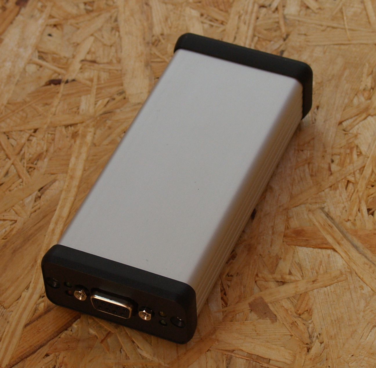
There are five
connectors on the PCB – serial port, radio, supply voltage, thermometer and
analogue input.
Serial
port:
2 - TxD
3 - RxD
4 - +5V (in
case of closed jumper)
5 - GND
9 - +5V (in
case of closed jumper)
Radio:
1 - +12 V in
(supply voltage)
2 - audio out
3 - GND
4 - GND
5 - audio in
6 - PTT
Power
supply:
Outer
connector GND
Center
connector +8V to +24V may be applied.
Thermometer
DS1820:
1 - +5V
2 - DQ
3 - GND
Analóg bemenet:
1 - GND
2 - U1 (U
input)
3 - U2 (V
input)
4 - U3 input
5 - U4 input
6 - U5 (T)
input
7 - +5V
D5 - DCD
D6 - GPS data
is correct
D7
- Equipment switched on/GPS data arrives
D8 - PTT
I recommend
to set as high data rate as possible on serial port since the MCU is able to
handleonly one peripheral at a time. If communication is too slow on the serial
port, the MCU has not enough time to decode every packet. I have set the data rate
to 38400 bps, so it does
not loose packets even in heavy traffic. It is a better solution of course, to
switch off monitoring using the MON OFF command. When one uses the equipment as
a repeater it is not necessary to send everything to the serial port. This is
necessary only when one wants to listen to data flow. In case one wants to see
in detail what goes on the radio channel, then display can be switched by the TRace
command. Then data is displayed in hexadecimal form instead of ASCII.
This
equipment does not require any kind of adjustment, other than the levels of
incoming and outgoing audio frequency signals. This APRS set may be fed from a
separate PSU or from the radio, using its supply points. In case GPS receiver
is not connected, its power consumption is negligible.
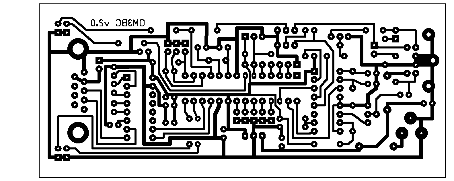
The size of
the completed PCB is 50 by
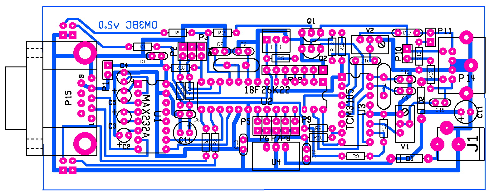
The real
size of PCB is 50 by
Program:
You must
see the following text after turning on the equipment if the data rate of the
terminal program was set right (38400 8N1):
BY OM3BC
FOR PIC18F26K22
Type HELP
for Info
Temperature
Sensor DS1820 Connected
cmd>
My setup is
like this:
Repeater running: 0 h.
Filter ON
ECHO ON
TEMPerature C
PERSistence 64
SLOTtime 30
TXDELAY 35
TXTAIL 2
GPS $GPRMC
TRace OFF
MONitor RCV
DIGIpeat ON
FILL in digi OFF
SUPPress ON
RDATA OFF
PARAM OFF
BEAcon Every 15
TAIL Every 5
SYMBOL />
HOLDoff 30
SERCOM 38400 Bd
SERGPS 4800 Bd
UNProto APBC48 V WIDE1-1 V WIDE2-2
MYCall OM3BC-2
DEAD CALLS
DEFS ATTAT
BTEXT 1 !4816.72N/01950.34E#PHG32304/A=000974 BCDIGI v.\z Qth Filakovo
BTEXT 2 !4816.72N/01950.34EyPHG32634/A=000974 BCDIGI v.\z APRS Repeater with PIC18F26k22 - http://www.om3bc.com
TTEXT Opel Astra mobil
OK
cmd>
PARM :OM3KKF-1 :PARM.Bat_A,Temp1,Temp2,Bat_B,Temp3,NC,NC,NC,NC,Camra,Chassis,Sun,door
UNIT :OM3KKF-1 :UNIT.Volts,Celsius,Celsius,Volts,Celsius,nc,nc,nc,nc,OPEN!,on,on,high
EQNS :OM3KKF-1 :EQNS.0,1,0,0,1,0,0,1,0,0,1,0,0,1,0
BITS :OM3KKF-1 :BITS.00001111,TEST PROJECT
if telemetry is active.
The beacon
text could look so with a temperature and voltage values:
BTEXT 1
!4815.91N/01949.21EyPHG32304/A=000577 APRS Repeater with PIC18F26K22 Temp. \t
in Filakovo U1: \u Volt, U2: \v Volt Runtime: \r h
Without box
it looks like this:
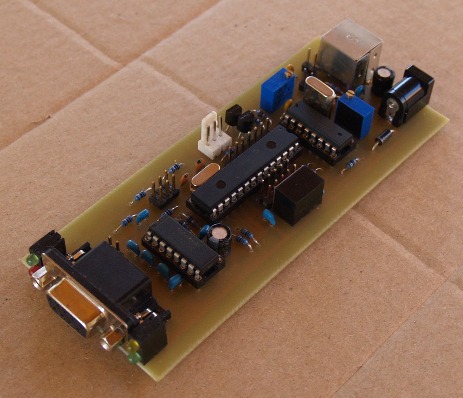
I have been
studying several similar equipment and I tried to include all solutions what I
found useful. There is only 1.5 kB empty from the 65 kB memory, so you may not expect
too many updates. This explanation is reticent, but you can find the most
important information for sure.
The
software may have some bugs. (Murphy’s Law is valid is my case too, stating there is no
perfect software, but if you happened to find one it must not be yours.)
If you have
any comment which could help my endeavors, just let me know and drop a message
to my E-mail address which can be found on my website.
I wish you
success to build this equipment.
The
drawings and the software in the MCU are the author's intellectual property.
Commercial use is not allowed without the written permission of the author!
Special thanks to HA6NN for translating this text.