There have already been several descriptions of
computer control of antenna rotators on the internet and on my website,
so I will not go into theory in detail now. The current description is
unique in that it is designed for AlfaSpid BIG-RAS drives. I decided to
buy a BIG-RAS rotator, but without my own electronics. There were two
reasons for this. On the one hand, there would be a big disgrace if I
couldn't make such a controller, and on the other hand, the feedback
about the original driver was not very good either. This rotator
provides only pulses, not an analog voltage that corresponds to a
specific position - such as Yaesu rotators - anyone who uses such a
rotator complains that after a certain time the actual position is not
in accordance with what the controller shows. Experience shows that
there is no such problem with this electronics. After considering the
above facts, the electronics described below were born.
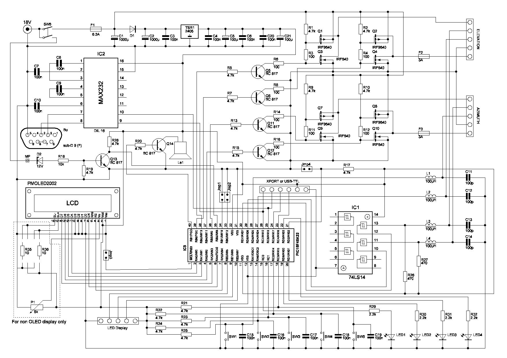
Schematic:

Description:
There is nothing special about connecting the controller. It is worth mentioning the double switch. One branch of the switch turns on the electronics itself, the other branch is used to timely signal the microprocessor that the device has been turned off. This is necessary so that the processor has time to save the current position. It is essential that the display shows the correct position even after switching on and that it is not necessary to calibrate the rotator after each switching on. I use an AMOLED display that does not require backlighting, but can also be used with any 2-line, 20-character display. Of course, in this case, trimmer P1 and resistors R35, R36 must be installed. Their value is determined by the required backlight intensity. The backlight output is not uniform for all displays, so the two resistors (or shorted if necessary) must be installed on the PCB according to the specific type. This controller is primarily intended for BIG-RAS rotators, but with small changes it can also be used for rotators with conventional analog feedback. In this case, IC1 does not need to be fitted, and R27 and R29 must be replaced by a short circuit (resistance 0 ohm). In this case, there will be 5 V on one pin of the connector and on the middle pin there should be an analog signal that goes to the processor on pins 27 and 28.
Software:
Two types of processors can be used. Either PIC18F4525 (or 4620) or PIC18F46K22 in a DIP40 package. Why these? Because I also had them in the drawer and I wanted to use them up. Of course, they can also be used in an SMD package, but then the printed circuit board needs to be redrawn.
The program is governed by the Yaesu Protocol, albeit in a fairly broad sense. Usable commands can be listed using the h <ENTER> or ? <ENTER> command. In this case we get as an answer:
----------------COMMAND LIST----------------
? Help Text
A CW/CCW Rotation Stop
B Antenna Direction EL
C Antenna Direction AZ
C2 Antenna Direction AZ&EL
D Down Direction Rotation
E UP/DOWN Direction Rotation Stop
F Set maximal position in azimuth: Faaa
F! Save current position as maximal position
F? Show maximal position in azimuth
G Set Offset In EL: Geee
G? Show Offset Constant for EL
H Help text
I Show parameters
JD Set Beeper on - Direct Current
JF Set Beeper on - Frequency
JN Set Beeper off
K Antenna Direction Setting In EL: Keee
L Counter Clockwise Rotation
M Antenna Direction Setting In AZ: Maaa
O Offset In AZ
O? Show Offset Constant
P Parking To: Paaa eee
P! Save current position as parking values
P? Show saved parking values
Q Precision 0.1 - 0.5 - 1.0 deg
R Clockwise Rotation
S All Stop
U Up Direction Rotation
V Softvare Version
W Antenna Direction Setting: Waaa eee
Y ECHO ON / OFF
Z Switch zero position to Nord / South
& Set maximum elevation (180 - flip on; 90 - flip off)
% Elevation control ON / OFF
* Max. elevation for overturning
# Emulation of GS232A / GS232B
< Azimuth calibration
^ Elevation calibration
/ Own coordinate - latitude
+ Own coordinate - longitude
> Own altitude
- OverTurning ON / OFF
= AutoTurning ON / OFF
aaa Is An Value For The Azimuth (0-360)
eee Is An Value For The Elevation (0-180)
If you are interested in which parameters are currently valid, you should send the command i <ENTER>. The response depends on your settings, something like this:
----------LIST OF PARAMETERS----------
Offset of azimuth: 28 deg
Offset of elevation: 7 deg
Maximum position of azimuth: 200 deg
Maximum position of elevation: 90 deg
Max. elevation for overturning: 90 deg
Elevation control: ON
Parking on AZ: 190 EL: 000
Type: GS232A
Zero position: South
COM port echo: ON
Beeper: Frequency
Precision: 0.5 deg
AutoTurn: ON
OverTurn: ON
Latitude: 48.265 deg
Longitude: 19.820 deg
Altitude: 204 m ASL
Software version: 14.0
The program accepts standard Yaesu commands, but can also interpret FOXDELTA commands. In addition, it receives standard GPGGA NMEA messages. Based on the data in it and our own coordinates, it calculates the direction of the high altitude balloon (or other object) and rotates the antenna.
When automatic rotation is activated, the rotator rotates automatically even after releasing the button. To do this, you must hold the button while it rotates at least 15 degrees in the horizontal direction or 5 degrees in the vertical direction. When released, the rotator rotates further to the start or end position or until you press one of the buttons again.
Because it is not always possible for larger antenna systems to take advantage of the possible 180 degree rotation in the vertical direction, it is advantageous if the antenna rotates not only 360 degrees horizontally, but at least 400-420 degrees. In this case, even if the satellite's orbit passes through the endpoint used (north-south), we can still monitor it and not have to wait for the antenna to rotate 360 degrees. The "-" command (OverTurn ON or OFF) is used for this. Unfortunately, these rotators are quite slow, and by the time the antenna rotates 360 degrees, the satellite is likely to be below the horizon.
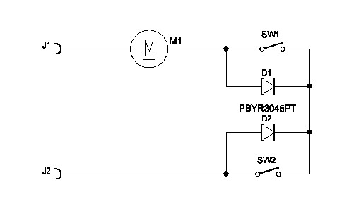
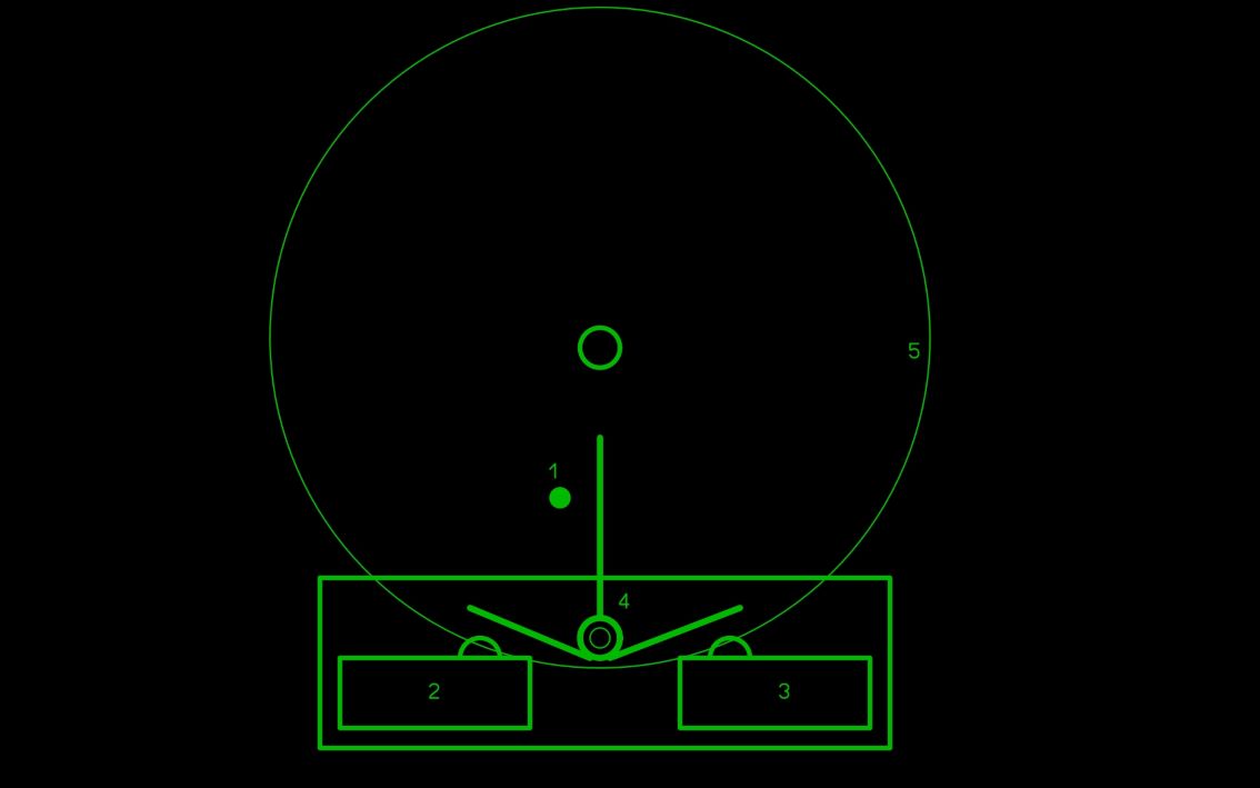
For the antenna calibration to work properly, a limit switch must be built into the rotary mechanism, which in the initial position stops the rotation in the horizontal direction. Such a limit switch is originally built in vertically, but in the horizontal direction - for reasons incomprehensible to me - it does not exist, so we have to build it ourselves. It's not too difficult to solve, but it requires a bit of creativity depending on who has what tools and limit switches available. In all cases, make sure that the switch is active in only one direction. One possible solution is shown in this figure. In this figure:
1 - vertical rod on the gear
2.3 - limit switches
4 - lever for switching limit switches
5 - gear
6 - auxiliary panel on which the lever shaft and limit switches are mounted
The advantage of this solution is that the limit switch is in both directions and the required range of rotation can be set by correct adjustment of the lever arms.
Limit switch connection:
Setting:
There are 5 buttons on the front panel. The left 2 buttons are for vertical rotation and the right 2 are for horizontal rotation. You can stop the rotation or enable or disable the rotation by briefly pressing the middle button. If the LED in the button is lit, the commands coming from the serial port are deactivated, the rotator responds only to the buttons. If the middle button is pressed for at least 2 seconds, the program enters the menu. In this case, you can scroll between the menu items with the two buttons on the left, use the two buttons on the right to enter the desired value and save it with the middle button. If you do nothing in the menu for 10 seconds, the program will automatically exit the menu.
Individual menu items:
1. rotates horizontally to the specified position
2. rotates vertically to the specified position
3. parking position in the horizontal direction
4. vertical parking position
5. offset horizontally
6. offset vertically
7. maximum position in the horizontal direction
8. maximum cant if overturning is permitted
9. COM port ECHO enable - disable - enable is not recommended
10. vertical rotation enable - disable
11. GS232A or GS232B communication protocol
12. maximum of vertical rotation - 90 or 180 degrees
13. Zero point to the south or north
14. sound generation - direct current, frequency or off
15. program version number
16. resolution of 0.1, 0.5 or 1.0 degree
17. own latitude coordinate
18. own longitude coordinate
19. own altitude
20. automatic rotation on or off
21. overturning - on or off
22. NMEA test on or off
23. Calibration AZIMUTH, ELEVATION
Calibration process:
The azimuth (button on the far left) can only be used if the limit switch is mounted !!!!! When you press the button, the antenna starts to rotate counterclockwise to the left. It rotates until it reaches the limit switch. In this case, the rotation stops. The program detects that there are no pulses at the input. Then it starts rotating the antenna to the right (clockwise). Rotates as many degrees as specified as the horizontal offset parameter. It stops here and takes this position as a starting point (north or south, depending on the setting). Altitude calibration works similarly in the vertical direction. Fortunately, there is a built-in limit switch.
Construction:
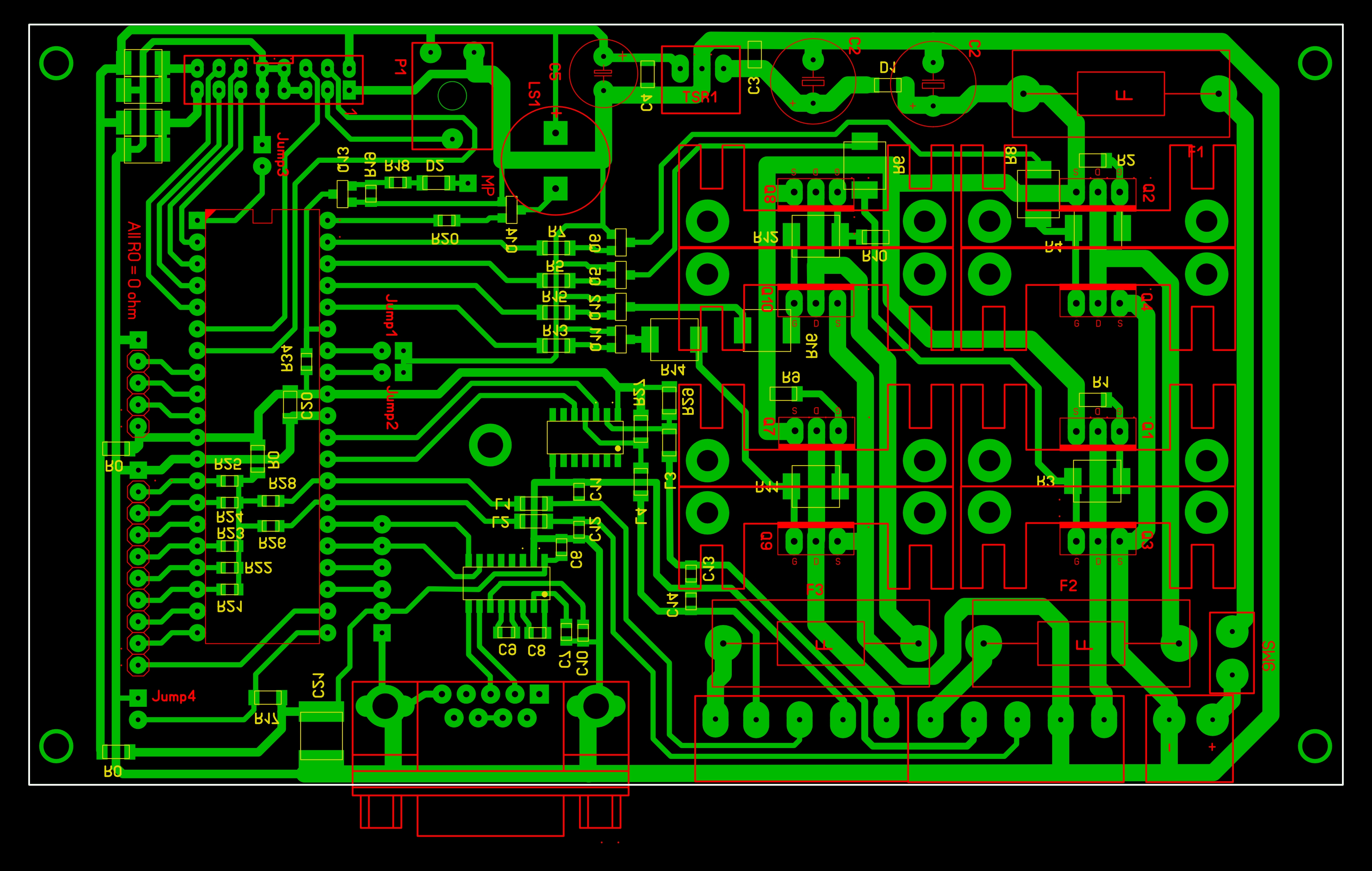
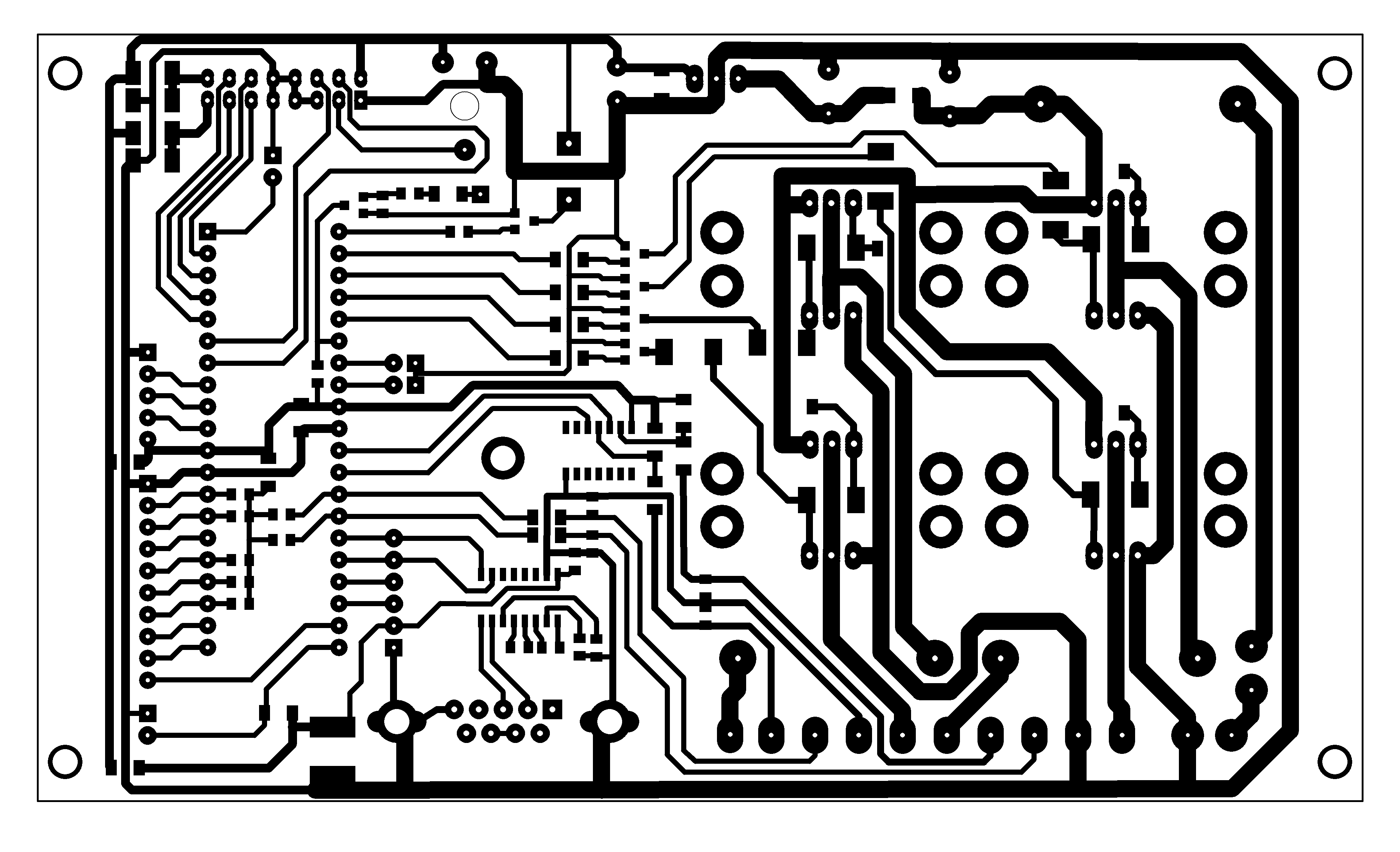
Because this electronics is not intended for mass production, SMDs and classical components are also mounted on the printed circuit board. The main aspect was that the printed circuit board was one-sided, so that the printed circuit board could be made by the "ironing" technique at home.
Mounting - main board (size: 154x89mm):
Mounting - display (size: 154x50mm):
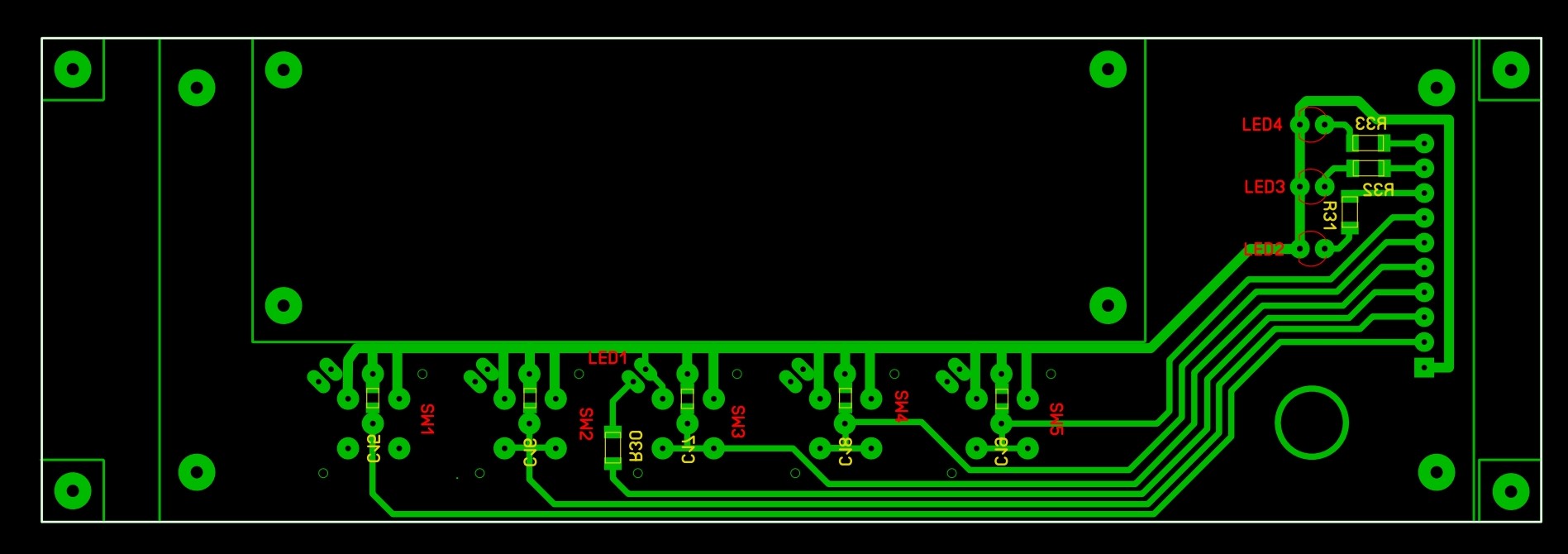
The display panel is connected to the main panel via a 10-core cable, while the display itself is connected via a 16-core cable.
schematic
main board - mounting
main - PCB
display - mounting
displej- PCB
firmware - PIC18F46K22 for OLED with SSD1311 chip
firmware - PIC18F46K22 for standard LCD with HD44780
gerber - main board
gerber - display
Schematic:
Description:
There is nothing special about connecting the controller. It is worth mentioning the double switch. One branch of the switch turns on the electronics itself, the other branch is used to timely signal the microprocessor that the device has been turned off. This is necessary so that the processor has time to save the current position. It is essential that the display shows the correct position even after switching on and that it is not necessary to calibrate the rotator after each switching on. I use an AMOLED display that does not require backlighting, but can also be used with any 2-line, 20-character display. Of course, in this case, trimmer P1 and resistors R35, R36 must be installed. Their value is determined by the required backlight intensity. The backlight output is not uniform for all displays, so the two resistors (or shorted if necessary) must be installed on the PCB according to the specific type. This controller is primarily intended for BIG-RAS rotators, but with small changes it can also be used for rotators with conventional analog feedback. In this case, IC1 does not need to be fitted, and R27 and R29 must be replaced by a short circuit (resistance 0 ohm). In this case, there will be 5 V on one pin of the connector and on the middle pin there should be an analog signal that goes to the processor on pins 27 and 28.
Software:
Two types of processors can be used. Either PIC18F4525 (or 4620) or PIC18F46K22 in a DIP40 package. Why these? Because I also had them in the drawer and I wanted to use them up. Of course, they can also be used in an SMD package, but then the printed circuit board needs to be redrawn.
The program is governed by the Yaesu Protocol, albeit in a fairly broad sense. Usable commands can be listed using the h <ENTER> or ? <ENTER> command. In this case we get as an answer:
----------------COMMAND LIST----------------
? Help Text
A CW/CCW Rotation Stop
B Antenna Direction EL
C Antenna Direction AZ
C2 Antenna Direction AZ&EL
D Down Direction Rotation
E UP/DOWN Direction Rotation Stop
F Set maximal position in azimuth: Faaa
F! Save current position as maximal position
F? Show maximal position in azimuth
G Set Offset In EL: Geee
G? Show Offset Constant for EL
H Help text
I Show parameters
JD Set Beeper on - Direct Current
JF Set Beeper on - Frequency
JN Set Beeper off
K Antenna Direction Setting In EL: Keee
L Counter Clockwise Rotation
M Antenna Direction Setting In AZ: Maaa
O Offset In AZ
O? Show Offset Constant
P Parking To: Paaa eee
P! Save current position as parking values
P? Show saved parking values
Q Precision 0.1 - 0.5 - 1.0 deg
R Clockwise Rotation
S All Stop
U Up Direction Rotation
V Softvare Version
W Antenna Direction Setting: Waaa eee
Y ECHO ON / OFF
Z Switch zero position to Nord / South
& Set maximum elevation (180 - flip on; 90 - flip off)
% Elevation control ON / OFF
* Max. elevation for overturning
# Emulation of GS232A / GS232B
< Azimuth calibration
^ Elevation calibration
/ Own coordinate - latitude
+ Own coordinate - longitude
> Own altitude
- OverTurning ON / OFF
= AutoTurning ON / OFF
aaa Is An Value For The Azimuth (0-360)
eee Is An Value For The Elevation (0-180)
If you are interested in which parameters are currently valid, you should send the command i <ENTER>. The response depends on your settings, something like this:
----------LIST OF PARAMETERS----------
Offset of azimuth: 28 deg
Offset of elevation: 7 deg
Maximum position of azimuth: 200 deg
Maximum position of elevation: 90 deg
Max. elevation for overturning: 90 deg
Elevation control: ON
Parking on AZ: 190 EL: 000
Type: GS232A
Zero position: South
COM port echo: ON
Beeper: Frequency
Precision: 0.5 deg
AutoTurn: ON
OverTurn: ON
Latitude: 48.265 deg
Longitude: 19.820 deg
Altitude: 204 m ASL
Software version: 14.0
The program accepts standard Yaesu commands, but can also interpret FOXDELTA commands. In addition, it receives standard GPGGA NMEA messages. Based on the data in it and our own coordinates, it calculates the direction of the high altitude balloon (or other object) and rotates the antenna.
When automatic rotation is activated, the rotator rotates automatically even after releasing the button. To do this, you must hold the button while it rotates at least 15 degrees in the horizontal direction or 5 degrees in the vertical direction. When released, the rotator rotates further to the start or end position or until you press one of the buttons again.
Because it is not always possible for larger antenna systems to take advantage of the possible 180 degree rotation in the vertical direction, it is advantageous if the antenna rotates not only 360 degrees horizontally, but at least 400-420 degrees. In this case, even if the satellite's orbit passes through the endpoint used (north-south), we can still monitor it and not have to wait for the antenna to rotate 360 degrees. The "-" command (OverTurn ON or OFF) is used for this. Unfortunately, these rotators are quite slow, and by the time the antenna rotates 360 degrees, the satellite is likely to be below the horizon.
For the antenna calibration to work properly, a limit switch must be built into the rotary mechanism, which in the initial position stops the rotation in the horizontal direction. Such a limit switch is originally built in vertically, but in the horizontal direction - for reasons incomprehensible to me - it does not exist, so we have to build it ourselves. It's not too difficult to solve, but it requires a bit of creativity depending on who has what tools and limit switches available. In all cases, make sure that the switch is active in only one direction. One possible solution is shown in this figure. In this figure:
1 - vertical rod on the gear
2.3 - limit switches
4 - lever for switching limit switches
5 - gear
6 - auxiliary panel on which the lever shaft and limit switches are mounted
The advantage of this solution is that the limit switch is in both directions and the required range of rotation can be set by correct adjustment of the lever arms.
Limit switch connection:
Setting:
There are 5 buttons on the front panel. The left 2 buttons are for vertical rotation and the right 2 are for horizontal rotation. You can stop the rotation or enable or disable the rotation by briefly pressing the middle button. If the LED in the button is lit, the commands coming from the serial port are deactivated, the rotator responds only to the buttons. If the middle button is pressed for at least 2 seconds, the program enters the menu. In this case, you can scroll between the menu items with the two buttons on the left, use the two buttons on the right to enter the desired value and save it with the middle button. If you do nothing in the menu for 10 seconds, the program will automatically exit the menu.
Individual menu items:
1. rotates horizontally to the specified position
2. rotates vertically to the specified position
3. parking position in the horizontal direction
4. vertical parking position
5. offset horizontally
6. offset vertically
7. maximum position in the horizontal direction
8. maximum cant if overturning is permitted
9. COM port ECHO enable - disable - enable is not recommended
10. vertical rotation enable - disable
11. GS232A or GS232B communication protocol
12. maximum of vertical rotation - 90 or 180 degrees
13. Zero point to the south or north
14. sound generation - direct current, frequency or off
15. program version number
16. resolution of 0.1, 0.5 or 1.0 degree
17. own latitude coordinate
18. own longitude coordinate
19. own altitude
20. automatic rotation on or off
21. overturning - on or off
22. NMEA test on or off
23. Calibration AZIMUTH, ELEVATION
Calibration process:
The azimuth (button on the far left) can only be used if the limit switch is mounted !!!!! When you press the button, the antenna starts to rotate counterclockwise to the left. It rotates until it reaches the limit switch. In this case, the rotation stops. The program detects that there are no pulses at the input. Then it starts rotating the antenna to the right (clockwise). Rotates as many degrees as specified as the horizontal offset parameter. It stops here and takes this position as a starting point (north or south, depending on the setting). Altitude calibration works similarly in the vertical direction. Fortunately, there is a built-in limit switch.
Construction:
Because this electronics is not intended for mass production, SMDs and classical components are also mounted on the printed circuit board. The main aspect was that the printed circuit board was one-sided, so that the printed circuit board could be made by the "ironing" technique at home.
Mounting - main board (size: 154x89mm):
Mounting - display (size: 154x50mm):
The display panel is connected to the main panel via a 10-core cable, while the display itself is connected via a 16-core cable.
schematic
main board - mounting
main - PCB
display - mounting
displej- PCB
firmware - PIC18F46K22 for OLED with SSD1311 chip
firmware - PIC18F46K22 for standard LCD with HD44780
gerber - main board
gerber - display